Featured

Electrical Vehicals

Hybrid Electrical Vehicles

Introduction

  • A hybrid electric vehicle (HEV) has two types of energy storage units, electricity and fuel.
  • Electricity means that a battery (sometimes assisted by ultracaps) is used to store the energy, and that an electromotor (from now on called motor) will be used as traction motor.
  • Fuel means that a tank is required, and that an Internal Combustion Engine (ICE, from now on called engine) is used to generate mechanical power, or that a fuel cell will be used to convert fuel to electrical energy.
  • In the latter case, traction will be performed by the electromotor only.
  • In the first case, the vehicle will have both an engine and a motor.

HEV classification

  • Depending on the drive train structure (how motor and engine are connected), we can distinguish between
    • parallel,
    • series
    • combined HEVs.
  • Depending on the share of the electromotor to the traction power, we can distinguish between
    • mild or micro hybrid (start-stop systems),
    • power assist hybrid,
    • full hybrid and plug-in hybrid.
  • Depending on the nature of the non-electric energy source, we can distinguish between combustion (ICE),
    • fuel cell, hydraulic or pneumatic power, and human power.
    • spark ignition engines (gasoline) or compression ignition direct injection (diesel) engine.
  • In the first two cases, the energy conversion unit may be powered by gasoline, methanol, compressed natural gas, hydrogen, or other alternative fuels.

Motors are the “work horses” of Hybrid Electric Vehicle drive systems. The electric traction motor drives the wheels of the vehicle.

  • Unlike a traditional vehicle, where the engine must “ramp up” before full torque can be provided, an electric motor provides full torque at low speeds.
  • The motor also has low noise and high efficiency. Other characteristics include excellent “off the line” acceleration, good drive control, good fault tolerance and flexibility in relation to voltage fluctuations.
  • The front-running motor technologies for HEV applications include –
    • PMSM (permanent magnet synchronous motor),
    • BLDC (brushless DC motor),
    • SRM (switched reluctance motor) and
    • AC induction motor.
  • A main advantage of an electromotor is the possibility to function as generator. In all HEV systems, mechanical braking energy is regenerated.
  • The max. operational braking torque is less than the maximum traction torque; there is always a mechanical braking system integrated in a car.

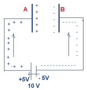
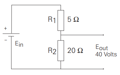
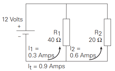
The battery pack in a HEV has a much higher voltage than the SIL automotive 12 Volts battery, in order to reduce the currents and the I2R losses.

Accessories such as power steering and air conditioning are powered by electric motors instead of being attached to the combustion engine. This allows efficiency gains as the accessories can run at a constant speed or can be switched off, regardless of how fast the combustion engine is running.

Especially in long haul trucks, electrical power steering saves a lot of energy.

1.  Types by drivetrain structure
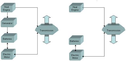
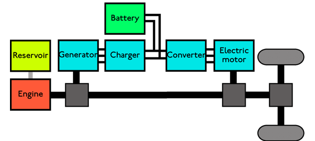
       a) Series hybrid

In a series hybrid system, the combustion engine drives an electric generator (usually a three-phase alternator plus rectifier) instead of directly driving the wheels. The electric motor is the only means of providing power to the wheels. The generator both charges a battery and powers an electric motor that

moves the vehicle. When large amounts of power are required, the motor draws electricity from both the batteries and the generator.

Series hybrid configurations already exist a long time: diesel-electric locomotives, hydraulic earth moving machines, diesel-electric power groups, loaders.

Structure of a series hybrid vehicle(below with flywheel or ultracaps as peak power unit)

Series hybrids can be assisted by ultracaps (or a flywheel: KERS=Kinetic Energy Recuperation System), which can improve the efficiency by minimizing the losses in the battery. They deliver peak energy during acceleration and take regenerative energy during braking. Therefore, the ulracaps are kept charged at low speed and almost empty at top speed. Deep cycling of the battery is reduced, the stress factor of the battery is lowered.

A complex transmission between motor and wheel is not needed, as electric motors are efficient over a

wide speed range. If the motors are attached to the vehicle body, flexible couplings are required.

Some vehicle designs have separate electric motors for each wheel. Motor integration into the wheels has the disadvantage that the unsprung mass increases, decreasing ride performance. Advantages of individual wheel motors include simplified traction control (no conventional mechanical transmission elements such as gearbox, transmission shafts, differential), all wheel drive, and allowing lower floors, which is useful for buses. Some 8×8 all-wheel drive military vehicles use individual wheel motors.

A fuel cell hybrid electric always has a series configuration: the engine-generator combination is replaced by a fuel cell.

Structures of a fuel cell hybrid electric vehicle

Weaknesses of series hybrid vehicles:

   The ICE, the generator and the electric motor are dimensioned to handle the full power of the vehicle. Therefore, the total weight, cost and size of the powertrain can be excessive.

   The power from the combustion engine has to run through both the generator and electric motor. During long-distance highway driving, the total efficiency is inferior to a conventional transmission, due to the several energy conversions.

Advantages of series hybrid vehicles:

   There is no mechanical link between the combustion engine and the wheels. The engine- generator group can be located everywhere.

   There are no conventional mechanical transmission elements (gearbox, transmission shafts).

Separate electric wheel motors can be implemented easily.

   The combustion engine can operate in a narrow rpm range (its most efficient range), even as the car changes speed.

   Series hybrids are relatively the most efficient during stop-and-go city driving.

Example of SHEV: Renault Kangoo.
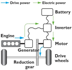
        b)Parallel hybrid

Parallel hybrid systems have both an internal combustion engine (ICE) and an electric motor in parallel connected to a mechanical transmission.

Structure of a parallel hybrid electric vehicle

Most designs combine a large electrical generator and a motor into one unit, often located between the combustion engine and the transmission, replacing both the conventional starter motor and the alternator (see figures above). The battery can be recharged during regenerative breaking, and during cruising (when the ICE power is higher than the required power for propulsion). As there is a fixed mechanical link between the wheels and the motor (no clutch), the battery cannot be charged when the car isn’t moving.

When the vehicle is using electrical traction power only, or during brake while regenerating energy,

the ICE is not running (it is disconnected by a clutch) or is not powered (it rotates in an idling manner).

Operation modes:

The parallel configuration supports diverse operating modes:

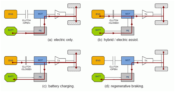
Some typical modes for a parallel hybrid configuration PE = Power electronics

TX = Transmission

  • electric power only: Up to speeds of usually 40 km/h, the electric motor works with only the energy of the batteries, which are not recharged by the ICE. This is the usual way of operating around the city, as well as in reverse gear, since during reverse gear the speed is limited.
  • ICE power only: At speeds superior to 40 km/h, only the heat engine operates. This is the normal operating way at the road.
  • ICE + electric power: if more energy is needed (during acceleration or at high speed), the electric motor starts working in parallel to the heat engine, achieving greater power
  • ICE + battery charging: if less power is required, excess of energy is used to charge the batteries. Operating the engine at higher torque than necessary, it runs at a higher efficiency.
  • regenerative breaking: While braking or decelerating, the electric motor takes profit of the kinetic energy of the he moving vehicle to act as a generator.

Sometimes, an extra generator is used: then the batteries can be recharged when the vehicle is not driving, the ICE operates disconnected from the transmission. But this system gives an increased weight and price to the HEV.

A parallel HEV can have an extra generator for the battery (left) Without generator, the motor will charge the battery (right)

Weaknesses of parallel hybrid vehicles:    Rather complicated system.

   The ICE doesn’t operate in a narrow or constant RPM range, thus efficiency drops at low rotation speed.

   As the ICE is not decoupled from the wheels, the battery cannot be charged at standstill.

Advantages of parallel hybrid vehicles:

   Total efficiency is higher during cruising and long-distance highway driving.    Large flexibility to switch between electric and ICE power

   Compared to series hybrids, the electromotor can be designed less powerful than the ICE, as it is assisting traction. Only one electrical motor/generator is required.

Example of PHEV:

Honda Civic. Honda’s IMA (Integrated Motor Assist) uses a rather traditional ICE with continuously variable transmission, where the flywheel is replaced with an electric motor.

Influence of scale: a Volvo 26 ton truck (12 ton own weight, 14 ton max load) equipped with 200 kg of batteries can drive on pure electric power for 2 minutes only! Because of space constraints, it is not possible to build in more batteries.

BMW 7Series ActiveHybrid.
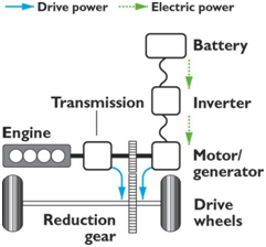
        c)Combined hybrid

Combined hybrid systems have features of both series and parallel hybrids. There is a double connection between the engine and the drive axle: mechanical and electrical. This split power path allows interconnecting mechanical and electrical power, at some cost in complexity.

Power-split devices are incorporated in the powertrain. The power to the wheels can be either mechanical or electrical or both. This is also the case in parallel hybrids. But the main principle behind the combined system is the decoupling of the power supplied by the engine from the power demanded by the driver.

Simplified structure of a combined hybrid electric vehicle

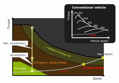
In a conventional vehicle, a larger engine is used to provide acceleration from standstill than one needed for steady speed cruising. This is because a combustion engine’s torque is minimal at lower RPMs, as the engine is its own air pump. On the other hand, an electric motor exhibits maximum torque at stall and is well suited to complement the engine’s torque deficiency at low RPMs. In a combined hybrid, a smaller, less flexible, and highly efficient engine can be used. It is often a variation of the conventional Otto cycle, such as the Miller or Atkinson cycle. This contributes significantly to the higher overall efficiency of the vehicle, with regenerative braking playing a much smaller role.

At lower speeds, this system operates as a series HEV, while at high speeds, where the series powertrain is less efficient, the engine takes over. This system is more expensive than a pure parallel system as it needs an extra generator, a mechanical split power system and more computing power to control the dual system.

Combined HEV with planetary unit as used in the Toyota Prius

Combined hybrid drive modes

Weaknesses of combined hybrid vehicles:

   Very complicated system, more expensive than parallel hybrid.

   The efficiency of the power train transmission is dependent on the amount of power being transmitted over the electrical path, as multiple conversions, each with their own efficiency, lead to a lower efficiency of that path (~70%) compared with the purely mechanical path (98%).

Advantages of combined hybrid vehicles:

Maximum flexibility to switch between electric and ICE power

   Decoupling of the power supplied by the engine from the power demanded by the driver allows for a smaller, lighter, and more efficient ICE design.

Example of CHEV: Toyota Prius, Auris, Lexus CT200h, Lexus RX400h.

2.  Types by degree of hybridization

Parallel and combined hybrids can be categorized depending upon how balanced the different portions are at providing motive power. In some cases, the combustion engine is the dominant portion; the electric motor turns on only when a boost is needed. Others can run with just the electric system operating.

Overview of Hybrid-powertrain concepts

        Strong hybrid ( = full hybrid)

A full hybrid EV can run on just the engine, just the batteries, or a combination of both. A large, high- capacity battery pack is needed for battery-only operation.

Examples:

The Toyota Prius, Auris and Lexus are full hybrids, as these cars can be moved forward on battery power alone. The Toyota brand name for this technology is Hybrid Synergy Drive. A computer oversees operation of the entire system, determining if engine or motor, or both should be running. The ICE will be shut off when the electric motor is sufficient to provide the power.

        Medium hybrid ( = motor assist hybrid)

Motor assist hybrids use the engine for primary power, with a torque-boosting electric motor connected in parallel to a largely conventional powertrain. EV mode is only possible for a very limited period of time, and this is not a standard mode. Compared to full hybrids, the amount of electrical power needed is smaller, thus the size of the battery system can be reduced. The electric motor, mounted between the engine and transmission, is essentially a very large starter motor, which operates not only when the engine needs to be turned over, but also when the driver “steps on the gas” and requires extra power. The electric motor may also be used to re-start the combustion engine, deriving the same benefits from shutting down the main engine at idle, while the enhanced battery system is used to power accessories. The electric motor is a generator during regenerative breaking.

Examples:

Honda’s hybrids including the Civic and the Insight use this design, leveraging their reputation for design of small, efficient gasoline engines; their system is dubbed Integrated Motor Assist (IMA). Starting with the 2006 Civic Hybrid, the IMA system now can propel the vehicle solely on electric power during medium speed cruising.

A variation on this type of hybrid is the Saturn VUE Green Line hybrid system that uses a smaller electric motor (mounted to the side of the engine), and battery pack than the Honda IMA, but functions similarly.

Another variation on this type is Mazda’s e-4WD system, offered on the Mazda Demio sold in Japan. This front-wheel drive vehicle has an electric motor which can drive the rear wheels when extra traction is needed. The system is entirely disengaged in all other driving conditions, so it does not enhance performance or economy.

        Mild hybrid / micro hybrid (= start/stop systems with energy recuperation)

Mild hybrids are essentially conventional vehicles with oversized starter motors, allowing the engine to be turned off whenever the car is coasting, braking, or stopped, yet restart quickly and cleanly.

During restart, the larger motor is used to spin up the engine to operating rpm speeds before injecting any fuel. That concept is not unique to hybrids; Subaru pioneered this feature in the early 1980s, and the Volkswagen Lupo 3L is one example of a conventional vehicle that shuts off its engine when at a stop.

As in other hybrid designs, the motor is used for regenerative braking to recapture energy. But there is no motor-assist, and no EV mode at all. Therefore, many people do not consider these to be hybrids, since there is no electric motor to drive the vehicle, and these vehicles do not achieve the fuel economy of real hybrid models.

Some provision must be made for accessories such as air conditioning which are normally driven by the engine. Those accessories can continue to run on electrical power while the engine is off.

Furthermore, the lubrication systems of internal combustion engines are inherently least effective

immediately after the engine starts; since it is upon startup that the majority of engine wear occurs, the frequent starting and stopping of such systems reduce the lifespan of the engine considerably. Also, start and stop cycles may reduce the engine’s ability to operate at its optimum temperature, thus reducing the engine’s efficiency.

Powertrain of a mild HEV

Examples:

BMW succeeded in combining regenerative braking with the mild hybrid “start-stop” system in their current 1-series model.

Citroën proposes a start-stop system on its C2 and C3 models. The concept-car C5 Airscape has an improved version of that, adding regenerative breaking and traction assistance functionalities, and supercapacitors for energy buffering.

        Plug-in hybrid (= grid connected hybrid = vehicle to grid V2G)

All the previous hybrid architectures could be grouped within a classification of charge sustaining: the energy storage system in these vehicles is designed to remain within a fairly confined region of state of charge (SOC). The hybrid propulsion algorithm is designed so that on average, the SOC of energy storage system will more or less return to its initial condition after a drive cycle.

A plug-in hybrid electric vehicle (PHEV) is a full hybrid, able to run in electric-only mode, with larger batteries and the ability to recharge from the electric power grid. Their main benefit is that they can be gasoline-independent for daily commuting, but also have the extended range of a hybrid for long trips.

Grid connected hybrids can be designed as charge depleting: part of the “fuel” consumed during a drive is delivered by the utility, by preference at night. Fuel efficiency is then calculated based on actual fuel consumed by the ICE and its gasoline equivalent of the kWh of energy delivered by the utility during recharge. The “well-to-wheel” efficiency and emissions of PHEVs compared to gasoline hybrids depends on the energy sources used for the grid utility (coal, oil, natural gas, hydroelectric power, solar power, wind power, nuclear power).

In a serial Plug-In hybrid, the ICE only serves for supplying the electrical power via a coupled generator in case of longer driving distances. Plug in hybrids can be made multi-fuel, with the electric power supplemented by diesel, biodiesel, or hydrogen.

The Electric Power Research Institute’s research indicates a lower total cost of ownership for PHEVs

due to reduced service costs and gradually improving batteries.

Some scientists believe that PHEVs will soon become standard in the automobile industry. Plug-in vehicles which use batteries to store electric energy outperform cars which use hydrogen as carrier for the energy taken from the grid. The following figures indicate the efficiencies of a hydrogen fuel cell HEV and a battery powered EV.

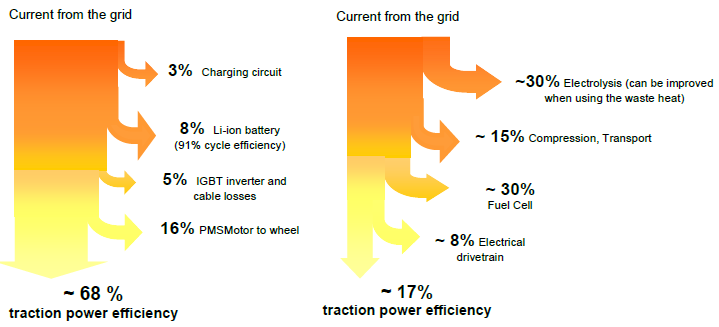
Traction power efficiency of a plugged EV.

Left a battery powered plug in EV (Mitsubishi Lancer Evolution MIEV)) Right a Fuel Cell EV (Mercedes NECAR 3)

For typical driving cycles, the achieved efficiencies are lower. The battery powered EV achieves efficiencies in the range of 50 to 60%. The hydrogen powered EV has a total efficiency of about 13% only at those drive cycles.

Examples:

Mercedes BlueZERO E-CELL PLUS (concept car): series HEV. Opel Ampera: series HEV.

Plug-in-Hybrid Opel Ampera

The Plug-in-Hybrid Volvo C30 (concept car) is a series HEV. It has a 1,6 liter gasoline/bio-ethanol ICE. A synchronous generator charges the Li-polymer battery (ca. 100 km autonomy) when the battery SoC is lower than 30%. There are four electric wheel-motors.

Plug-in-Hybrid Volvo C30

3.  Types by nature of the power source

        Electric-internal combustion engine hybrid

There are many ways to create an electric-internal combustion hybrid. The variety of electric-ICE designs can be differentiated by how the electric and combustion portions of the powertrain connect (series, parallel or combined), at what times each portion is in operation, and what percent of the power is provided by each hybrid component. Many designs shut off the internal combustion engine when it is not needed in order to save energy, see 2.3.

        Fuel cell hybrid

Fuel cell vehicles have a series hybrid configuration. They are often fitted with a battery or supercapacitor to deliver peak acceleration power and to reduce the size and power constraints on the fuel cell (and thus its cost). See 1.1.

        Human power and environmental power hybrids

Many land and water vehicles use human power combined with a further power source. Common are parallel hybrids, e.g. a boat being rowed and also having a sail set, or motorized bicycles. Also some series hybrids exist. Such vehicles can be tribrid vehicles, combining at the same time three power sources e.g. from on-board solar cells, from grid-charged batteries, and from pedals.

The following examples don’t use electrical power, but can be considered as hybrids as well:

        Pneumatic hybrid

Compressed air can also power a hybrid car with a gasoline compressor to provide the power. Moteur Developpement International in France produces such air cars. A team led by Tsu-Chin Tsao, a UCLA mechanical and aerospace engineering professor, is collaborating with engineers from Ford to get Pneumatic hybrid technology up and running. The system is similar to that of a hybrid-electric vehicle in that braking energy is harnessed and stored to assist the engine as needed during acceleration.

        Hydraulic hybrid

A hydraulic hybrid vehicle uses hydraulic and mechanical components instead of electrical ones. A variable displacement pump replaces the motor/generator, and a hydraulic accumulator (which stores energy as highly compressed nitrogen gas) replaces the batteries. The hydraulic accumulator, which is essentially a pressure tank, is potentially cheaper and more durable than batteries. Hydraulic hybrid technology was originally developed by Volvo Flygmotor and was used experimentally in buses from the early 1980s and is still an active area.

Initial concept involved a giant flywheel (see Gyrobus) for storage connected to a hydrostatic transmission, but it was later changed to a simpler system using a hydraulic accumulator connected to a hydraulic pump/motor. It is also being actively developed by Eaton and several other companies, primarily in heavy vehicles like buses, trucks and military vehicles. An example is the Ford F-350 Mighty Tonka concept truck shown in 2002. It features an Eaton system that can accelerate the truck up to highway speeds.

Featured

Interview Questions & Answares (Electrical Engineering )

1)Why Current through an Inductor lags Behind Voltage?

For understanding the reason, why current through and Inductor lags behind Voltage across the Inductor, we will first go mathematically then we will understand the concept analytically. Let us consider a purely inductive circuit as shown in figure below.

As shown in the figure above, an inductor of value L Henray is connected with an AC supply source V = VmSinωt.

According to Kirchhoff’s loop law, the voltage induced across the Inductor will be equal to the supply voltage and therefore we can write as below.

VmSinωt = Voltage induced across Inductor

But induced emf in an Inductor is Ldi/dt and therefore,

VmSinωt = Ldi/dt

⇒ Ldi = VmSinωtdt

Integrating both sides, we get

i = (Vm/wL)Cosωt + C

where C is some constant.

Now, as the average value of Cosωt over one time period is zero and the supply voltage in our discussion in sinusoidal, therefore we expect the current to be also sinusoidal. Therefore, the value of constant C must be zero here in our case.

⇒ i = (Vm/ωL)Cosωt

⇒ i = (Vm/ωL)Sin (ωt – π/2)

Thus from the above expression, we observe that the phase difference between the applied voltage V = VmSinωt and current through Inductor i = (Vm/ωL)Sin (ωt – π/2) is π/2. This means that the current through an inductor is lagging behind the applied voltage V by an angle of 90°.

This was mathematical calculation to show that current through an inductor is lagging the supply voltage by an angle of 90°. But now we will discuss the same aspect but in analytical way.

For analytical discussion we will assume steady state condition.

As we know that when a current flows through a solenoid, a magnetic field is created by the solenoid which remain confined inside the solenoid only. Now suppose, the current through the solenoid is changing with time, that simply means that magnetic flux will also change resulting into change in magnetic flux. As the coil of solenoid is linking with this changing magnetic flux, an emf will be induced in the solenoid in such a direction to oppose the cause in occurrence with Lenz’s Law. Here the cause is current flowing through the solenoid, therefore the emf will be induced in such a direction to oppose the flow of current. Here solenoid is Inductor.

Let us consider

  1. steady state where the supply voltage V is going positive from zero (point P in the figure below). In this case, as the back emf of inductor will also be zero and therefore the current flowing through the circuit will be maximum.
  2. Now as the supply voltage increases in positive direction, back emf of inductor will also rise but in opposite direction due to which the current flow through the circuit will start decreasing and will become zero when the back emf of inductor becomes maximum equal to the supply voltage as at that time supply voltage become maximum positive (point Q in figure below).
  3. After that, the supply voltage will start decreasing from it maximum value, but as the back emf of inductor is maximum but opposite in direction, the current through the circuit will change its direction. As the current in the circuit is flowing in opposite direction, the back emf of inductor will start building up in opposite to the direction of flow of current and hence net back emf of inductor will decrease and will reach to zero when supply voltage reaches zero. At this point (R) maximum current through the circuit will flow.

Thus we see that, it is the generation of back emf in the inductor which forces the current flowing through it to lag by applied voltage. 

2) Why Starting current is high in a DC Motor?

The starting current is high as there is no back EMF or counter EMF present in the armature circuit because at starting counter EMF is zero. … It’s armature has very less resistance due to this it need more current at starting time. Hence DC starters are used to limit the starting current of motor.

3)Why Capacitor block DC & allow AC current?

All of us know that a Capacitor do not allow DC current to pass through it but allows AC current. In this post we will discuss this kind of behavior of Capacitor.First we will consider DC supply connected to a parallel plate capacitor as shown in figure below.

Let the capacitance be C. So as we connect the one of parallel plate capacitor to the positive terminal of battery and another plate to the negative terminal of battery, a potential difference exists.

Here in our case, the potential difference between plate A of capacitor and positive terminal of battery = 5 V. Because of this potential difference, positive charge will start moving from the positive terminal of battery to the plate A of capacitor. Mind that charge is not supplied by the battery rather is the mobile electron of the connecting wire. Thus, the charge on the Plate A of Capacitor will be increasing from zero value to some finite value till the potential of plate A becomes equal to the potential of positive terminal of the battery. After this no further movement of charge will occur from positive terminal of battery to the plate A. Thus we can say at steady state, potential of plate A = 5 V and no further movement of charge i.e. no current.

Similarly, the initial charge on the plate B of Capacitor is zero but as soon as we connect the plate B to the negative terminal of the battery, a potential difference will exists due to which electrons will move from negative terminal of battery to the plate B (mind that potential of plate B is zero while that of negative terminal of battery is -5 V and electrons move from low potential to high potential.). This movement will take place till the potential of plate B becomes equal to the potential of negative plate of battery. Thus in steady state, the potential of plate B = -5 V and no further movement of charge i.e. no current.

But note that DC current is flowing through the capacitor till the transient state lasts i.e. till the time the potential difference between the plates of capacitor and battery becomes zero.

Thus we observe that in steady state, there is no potential difference between the plates of capacitor and the battery terminals to drive current. That is why a Capacitor is said to Block the DC current.

How Capacitor Allows AC

Let V = VmSinωt and its curve will be as shown in figure.

When AC voltage is applied across the plates of parallel plate capacitor, plate A will start to get charge till VPK and plate B of capacitor will get negative charge.

But after peak voltage VPK, as the voltage of source is less than the voltage across the capacitor plates, the capacitor will start discharging till source voltage becomes zero.

After that as the source voltage is going negative, the Plate A will now become negatively charged while plate B will be positively charged till negative peak of source voltage but once negative peak of applied voltage crosses, the capacitor will again start to discharge as the potential difference across the plates of capacitor is more than the source voltage.

In this way Capacitor continuously charge and discharge for applied AC and hence we say Capacitor is allowing AC to flow.

Mind that when the applied voltage is at its peak, the capacitor is fully charged and therefore no movement of charge will take place at this instant and hence current through the capacitor is zero when the applied voltage is its peak. Similarly, when the applied voltage is zero, the capacitor is fully discharged and therefore as the voltage increases just from its zero voltage, charging current will start flowing from source to the plates of capacitor but as the charge gets accumulated on the plate, the potential of plate rises resulting in decrease in potential difference between the plates and the source. Because of this the magnitude of charging current decreases and becomes zero when the potential of plates of capacitor becomes equal to the source potential. This is why, we say Capacitor takes leading current.

4) Why LT motors are Delta connected & HT motors are Star connected?

In industries Low Tension i.e. low voltage Motors like Motors supplied by three phase 415 V are normally have Stator connected in Delta while High Tension i.e. Motors supplied by high voltage like 6.6 kV have Stator connected in Star configuration. The reason behind this is technical while making the Motor economical.

Following are the main reasons due to which high voltage Motors stator are connected in Star:

  • As the Stator winding of Motor is to be connected with high voltage, it is better to configure the Stator in STAR as in this configuration, the phase current remains the same as the line current but the phase voltage reduces by to Vph = Vline/1.732 which means that insulation requirement from phase winding will be less.
  • The second most important reason is that, starting current for Motors is 6 to 7 times of full load current. So start-up power will be large if HT motors are delta connected. It may cause instability i.e. voltage dip in case of small Power System. In STAR connected HT Motors starting current will be less compared to delta connected motor as voltage is Vphand current is line current. So starting power and starting torque are reduced.
  • As current is less in STAR configuration, copper (Cu) required for winding will be less.

Following are the main reasons due to which low voltage Motors stator are connected in Delta:

  • In Delta connection, the insulation requirement will not be problem as voltage level is less in LT Motors.
  • Starting current will not be problem as starting power in all will be less. So no problem of voltage dips.
  • Starting torque should be large, as motors are of small capacity and hence Stator should be connected in Delta to have more current and hence more starting torque.

5) What happen when one of the 3 phases of supply voltage of 3 phase induction otor is lost?

When a three phase motor looses one of the phase supply voltage then it is called Single Phasing.

 Single Phasing a case when any one phase out of the three phases fails. Since one of the phases is now disconnected, current through other two phases will increase to produce the desired torque.

The motor will run but would not be able to drive rated load. The uneven torque results in abnormal noise and vibration in motor.

In order to compensate, the motor starts drawing more amount of current heating the motor even in some cases could burn the motor.

Once the motor is started, it continues to run, at least for some more time. What happens in long term depends upon the load.

  • If motor is operating at or less than 33%, it will continue to operate without any harm.
  • Due to single phasing the current in the remaining two phases increases and it is approximately 2.4 times the normal current value.

  • If motor is operating at slightly higher than 33% load, motor will continue to operate, but it will draw current more than its rated value. 
  •  The motor temperature will start increasing.
  • If thermal overload relay is provided in the motor starter, it will stop the motor before motor burns.
  • But if thermal overload rely is not provided, motor may get burnt. 
  • If motor is operating at higher load near to the rated load, motor speed will drop gradually to zero.
  • It may take 1 to 30 seconds, depending upon amount of the overload and inertia of the load connected.
  • For high inertia loads, it may take even more time to reduce the speed to zero. In this case thermal overload relay may stop the motor current or fuse may blow.
  • If thermal overload relay / fuses are not provided, motor may get but burnt.

6) What is difference between locked rotor current and starting current?

  1. Locked Rotor current and Starting current of induction motor seems to be the same thing at first glance but it is not so.
  2. These are two different terms having different meaning and significance. In this post we will discuss the difference between the locked current and starting current of induction motor.
  3. Locked rotor current is basically the current drawn by the motor at its rated voltage when its rotor is kept stationary or in other words rotor is not spinning or rotating.
  4. So when we start a motor, its rotor is already at rest.
  5. This means, starting current and locked rotor current should be same. Isn’t it? No, it is not so.

How?

  1. See, motor can be started using one of the various starting methods.
  2. If the motor is started using Direct Online (DOL) method, then the voltage applied at its terminal will be rated voltage of motor.
  3. As the rotor is at rest during starting and voltage is rated voltage, the starting current will be equal to locked rotor current.
  4. But if any other starting method viz. Star Delta / Soft Startis used, then motor will be started at a lower voltage (lower than the rated voltage), hence starting current will be less than the locked rotor current.
  1. Another important difference between them is that locked rotor can be anytime during the operation of the motor.
  2. For example, consider a motor running normally under its rated load.
  3. A sudden increase in load beyond its rating will cause increase in motor current and hence increased motor torque.
  4. But if the load torque requirement is more than the motor torque, the motor current will further increase to increase its torque and will reach maximum (equal to pull out torque).
  5. If still the load torque requirement is more than the pull out torque, the motor speed will decrease to zero.
  6. This is the case of locked rotor. There are various other causes like jamming of motor bearing, load jamming, single phasing of motor etc.

Thus locked rotor current can be drawn anytime depending on when the rotor is being halted or stalled while the starting current is only taken during the motor starting.

Locked rotor current should not persist for a long time else it may lead to insulation failure due to overheating or may lead to buring of stator / rotor.

6) Why does current lead voltage in a capacitive circuit?


There’s a mathematical explanation, and there’s an intuitive one. Let’s do the mathematical explanation first:

Looking at the circuit above, we know for a capacitor that

Q = CV

where Q is the charge on the capacitor’s plates, C is its capacitance, and V is the voltage across the capacitor.

We also know that I, the electric current is the flow of electric charge with time:

dQ/dt

Combine these two, and for a capacitor, we see:

I = dQ/dt = C*dV/dt

Now, if we have a sinusoidal input voltage, we can calculate the current across the capacitor as a function of the voltage:

V(t) = sin(t)
I(t) = C*dV(t)/dt = C*cos(t)

But cos(t) is just sin(t) plus pi/2 radians (90 degrees). So our final equations for the capacitor circuit above become:

V(t) = sin(t)
I(t) = C*cos(t) = C*sin(t + pi/2)

So for a sinusoidal input voltage, we see that we also get a sinusoidal current, but the current leads the voltage by pi/2 radians (90 degrees)!

And the intuitive explanation:

Intuitively, we know the current through a capacitor can change instantaneously, but since its voltage is determined by the sum of all the charge that has flowed through it, the voltage reacts less quickly. For example, a large but very short spike in current may lead to only a small change in the voltage. This means that, for a capacitor, changes in voltage will always lag behind changes in current.

7)Why does current lead voltage in a capacitive circuit?

It is a property of a capacitor to resist change in voltage because of its charge storage. When current changes, it takes some time for voltage to catch up.

Mathematically:

I = C. dV/dt

Suppose capacitor is connected to a sinusoidal source.

V = sin(wt)

I = wC.cos(wt)

If you plot the graphs, you will notice that the cosine function leads the sine function by 90 degrees.

In case of inductor, it resists change in current. So current lags voltage.

8)What happens when we apply ac supply to capacitor?

The basics of capacitance.

If we take two metal plates, separate them with a dielectric (insulator), and apply a DC voltage between the plates, current will not be able to cross the dielectric. However, a surplus of electrons will build up on the plate connected to the negative terminal of the voltage source, and shortage of electrons will occur on the plate connected to the positive terminal. The voltage source will try to

If we take two metal plates, separate them with a dielectric (insulator), and apply a DC voltage between the plates, current will not be able to cross the dielectric. However, a surplus of electrons will build up on the plate connected to the negative terminal of the voltage source, and shortage of electrons will occur on the plate connected to the positive terminal. The voltage source will try to force electrons into one plate (negative terminal) and draw them out of the other (positive terminal).

At some point in time, these plates will become completely saturated; no further electrons can be forced into the negative plate, and no more electrons can be drawn from the positive plate. At this point, the plates have an electrical potential equal to that of the voltage source. In fact, the plates now act like a second voltage source, one in parallel with the first but with the opposite polarity. Fig. 1 shows the equivalent circuit. Obviously, since these opposing voltages are equal, they cancel each other out, and no current can flow between the voltage source and the plates in either direction. The plates are said to be charged.

What happens if the voltage source is removed from the circuit? The answer is that the plates will remain charged because there is no place for the electrons on the negative plate to go. Similarly, there is no place for the positive plate to draw electrons from. In effect, the voltage is stored by the plates. [ILLUSTRATION FOR FIGURE 2 OMITTED].

Replacing the missing voltage source with a resistor, as shown in Fig. 3, provides a current path for the excess electrons stored on the negative plate to flow to the positively charged plate. This current flow will continue until both plates are returned to an electrically neutral state. This is called discharging the plates.

Such a device as noted above (two conductive plates separated by a dielectric) is called a capacitor. It’s used to store electrical energy. (Note: At one time a capacitor was known as a condenser, but this term has fallen from use.)

A capacitor can’t hold a charge indefinitely. Even air can conduct some current, so the charge will slowly seep off into the air. There will also be some leakage through the dielectric. All other factors being equal, the lower the internal leakage, the better the capacitor.

9)Residual Current Circuit Breaker?

RCCB (Residual Current Circuit Breaker) falls under the category of wide range of circuit breakers. As we know there are several types of miniature circuit breakers like MCCB which works on different operational principle and has different safety purposes.
Function: Residual Current Circuit Breaker is essentially a device which senses current and disconnects any low voltage (unbalanced current) circuit whenever there is any fault occurs.
Purpose: Residual Current Circuit Breaker basically is installed to prevent human from shocks or death caused by shocks. It prevents accidents by disconnecting the main circuit within fraction of seconds.

10) How Residual Current Circuit Breaker Works?

It has very simple working based on Kirchhoff’s Current Law ie the incoming current in a circuit must be equal to the outgoing current from that circuit. This circuit breaker is made such that whenever a fault occurs the current balance of line and neutral did not matches (imbalance occurs, as the fault current finds another earthing path of current).
Its circuit is made such that an every instance it compares the value of incoming and outgoing circuit current. Whenever it is not equal, the residual current which is basically the difference between the two currents actuates the circuit to trip/switch off.

The basic operating principle lies in the Toroidal Transformer shown in the diagram containing three coils. There are two coils say Primary (containing line current) and Secondary (containing neutral current) which produces equal and opposite fluxes if both currents are equal.
Whenever in the case there is a fault and both the currents changes, it creates out of balance flux, which in-turn produces the differential current which flows through the third coil (sensing coil shown in the figure) which is connected to relay.

The Toroidal transformer, sensing coil and relay together is known as RCD – Residual Current Device.
Test Circuit:
The test circuit is always included with the RCD which basically connects between the line conductor on the load side and the supply neutral. It helps to test the circuit when it is on or off the live supply. Whenever the test button is pushed current starts flowing through the test circuit depending upon the resistance provided in this circuit. This current passes through the RCD line side coil along with load current. But as this circuit bypasses neutral side coil of RCD, there will be an unbalance between the line side and neutral side coil of the device and consequently, the RCCB trips to disconnect the supply even in normal condition. This is how the test circuit tests the reliability of RCCB.

Types of Residual Current Circuit Breaker

2 Pole: It is for single phase line consisting of one live and one neutral wire slot in it.
4 Pole: It is designed for three phase line consisting of 4 slots where three phase wires and a neutral wire can be connected.
Conclusion:
Hence it provides a real time protection device for major circuits used commercially in industries and other high voltage commercial places where there is a always a risk of shocks and accidental deaths due to it.

11)Earth Leakage Circuit Breaker (ELCB)?

Introduction

In my last article I told you about Residual Current Circuit Breaker (RCCB). Today we will take a look at another important type of circuit breaker called – Earth Leakage Circuit Breaker (ELCB). An ELCB is another different class of Circuit Breakers with a specific function.

ELCB : what purpose?

An Earth Leakage Circuit Breaker is a safety device used in Electrical circuits with high Earth impedance to prevent the risk of Electrical shock. Unlike previously studied RCCB, an ELCB is a voltage operated device.
ELCB detects small stray voltages across metal enclosures of electrical installations and interrupts the circuit if the voltage level exceeds danger threshold.

Earth Leakage Circuit Breakers were invented almost 60 years ago and once quite widely used in electrical installations. However, since the invention of RCCB – an improved protection device, the use of ELCBs has come down.

Thus, the main purpose of ELCB is to detect Earth leakages and prevent injury to human beings from electrical shocks.

ELCB : how does it protect?

Although use of ELCB is taken over by current operated RCCB, it is interesting to study the working principle of Earth Leakage Circuit Breaker. Figure 1.0 below depicts the schematic of this device.

As depicted in the picture, the device consists of double pole switch connecting the supply and load sides. This double pole switch is internally connected to a solenoid trip coil. The trip coil is connected between Earth and the exposed metallic frame of the electrical installation. As seen in the picture, Terminal E of the trip coil is connected to Earth electrode and Terminal F is connected to metallic enclosure.

During normal operation, the double pole switch is closed and the current flows from supply to load side through the two lines (Phase, Neutral). During this period, there is no current flowing to earth between terminal F and E. Therefore the voltage between terminal E and F is negligible (almost Zero).

In case of a fault condition, the voltage on terminal F connected to exposed metal work rises up and the voltage at terminal E is at zero potential. Thus, there rises a potential difference between terminals E and F. This causes the connected trip coil to operate. The movement of trip coil then opens up the double switch and thus breaks the circuit.

There is a test button seen. It is used to test the operation of ELCB. When it is pressed, it temporarily connects the terminal F to line via test resistor. It disconnects the supply back to metal enclosure so as to avoid dangerous electrical current back to the metallic enclosure.

Advantages of ELCB over RCCB

One major advantage of ELCB over RCCB is that it is less sensitive to fault conditions over RCCB, hence it has less occurrences of nuisance tripping.

Disadvantages of ELCB

If the electrical installation’s earth rod is placed close to another earth rod of a building, then a high earth leakage current from other building can raise the local ground potential and cause a voltage difference across the two earths, again tripping the ELCB.

Nuisance tripping may cause during thunderstorms due to lightening strikes.

ELCBs do not detect fault current that doesn’t pass through connected earth rod.
E.g. a person coming in direct contact with live conductor. Hence in such cases, ELCB does not offer any protection.

Leaky appliances such as Water heaters, immersion heaters may cause leakage current to pass through F terminal connected to ground and may cause nuisance tripping.

12) How a electricity tester works?

Working of a Phase or Line Tester:

When we touch mouth (flat end of the Metallic rod) of Phase or Line tester with naked Live / hot wire whereas one of our finger touch the metallic Cap Screw or Clip of Phase/Line Tester, then circuit is completed and current start to flow in Metallic rod.

Metallic rod is connected to the resistor which reduces high current to a safe value. The reduced Current passes through Neon bulb which is connected to (metallic spring). Metallic spring is connected with metallic Cap screw which is in contact of our fingers. A very small current passes through our body to earth and complete the circuit. When circuit is completed, current starts to flow and the filament of neon bulb starts glowing. This indicates that the touched wire with Phase/Line Tester mouth is Phase/Line/Hot.

(Good to Know: Phase, Line, Hot, Live and Positive are the same terms)

If we perform the same action as mentioned above, and Neon bulb does not glow, it means that is a Neutral Wire/Conductor.

13)What happens if you put a discharged capacitor and a light bulb in parallel and connect it to a battery?

  1. At first, the capacitor acts like a short and all the current the battery can supply goes into the capacitor, with almost none going into the resistive light bulb.
  2. As the capacitor charges, it acts more resistive, so more current flows into the light bulb.
  3. Eventually, the capacitor reaches full charge and acts like a very large resistor, so almost all the current goes through the light bulb and lights it to full brightness. That is, if the voltage rating of the light bulb is the same as the voltage of the battery.
  4. So, the light bulb starts dark, slowly increases in brightness until it reaches full brightness.
  5. Depending on the capacitance of the capacitor, the light bulb will reach full brightness in much less than a second, to minutes, or even hours.

14)Will Bulb lit when connected in series with capacitor in AC & DC both supply?

Current flows through a capacitor in series with a load when the voltage of the capacitor varies. Since you do not say much about the kind of light bulb, the value of the capacitor, and the kind of source you have I must remain general in my answer:

  1. The higher the capacitance, the higher the current, the brighter the bulbs’ light
  2. The higher the frequency of the AC power source, the higher the current and the brightnes
  3. On a DC source the current will flow only for a limited short time
  4. The higher the voltage of the power source, the higher the brightnes
  5. The higher the impedance of the bulb, the lower the current, and the higher the efficiency of the bulb the higher the brightnes
  6. Light bulbs have highly non linear impedances, and LED lamps are mostly even more non-linear. So not knowing more about your light bulb and your power supply I cannot make any prediction on how it behaves exactly, and what is needed to make it shine

15)In an AC induction motor, is there any back-EMF generated inside the stator windings?

YES! Stator winding is nothing but a coil in essence. When AC power is applied across any coil of wire, a back emf is produced within the coil which opposes the applied voltage and limits the applied current which causes the applied current to lag behind the applied voltage.

The reason for the production of back emf is the cutting of flux through the coil. When current flows through the coil, flux is produced from zero the max. This growth of flux from zero to max is just like movement of flux lines as they spread out. This movement crosses the coil and creates emf according to Faraday’s law of electromagnetic induction.

16)An electric lamp connected in a series with a capacitor and an AC source is glowing with certain brightness. How does brightness of the lamp change in reducing capacitance and frequency?

This circuit configuration is essentially a voltage divider that is dependant upon the frequency.

The reactance of the capacitor changes with frequency. Increase the frequency and the reactance goes down. Decrease the frequency and the reactance goes up.. The reactance is expressed in Ohms,

The lower the frequency the more voltage is lost across the capacitor and less voltage is across the lamp. So its brightness will change with frequency.

Assertion: An electric lamp connected in series with a variable capacitor and ACAC source, its brightness increases with increases in capacitance.
Reason: Capacitive reactance decrease with increases in capacitance of capacitor.

16)What happens if current transformer gets saturated?

When current transformer gets saturated they no longer supply secondary current proportional to supplied primary current. Depending on the level of saturation the measured current on the secondary is much smaller than the value present in the primary.

The non-proportional secondary current under saturation condition is caused due to following reasons;

  1. Large primary current due to fault condition
  2. High burden (VA) on secondary side
  3. An open circuit condition occurred on the secondary side of CT

17)How does exactly CT saturate?

When supplied current in primary side is multiple times of its nominal current value(In), then the magnetic core does not respond to further increase in magnetic flux as all magnetic domains on a ferromagnetic material are already aligned and thus does not respond to any further increase in the flux. Once the CT saturates the resultant secondary current is full of harmonics and it is highly distorted.

Current transformer saturation leads to malfunction of protection devices as the measured current does not correspond to the current on the system.

18)What happens if we open the secondary of a current transformer?

Working principle of the current Transformer:

The current transformer works on the principle of electromagnetic induction. When alternating current flows in the primary winding of CT, the primary current generates a magnetic field (H= NI) in the core of CT. The generated magnetic field set up a magnetic flux in the core. The magnetic flux links to the secondary winding of CT mounted around the core, and thus linked flux induces the voltage in the secondary winding of CT,

The secondary winding of CT is connected to the burden (measuring instrument or protective relay). If the secondary of CT is connected to the burden, the alternating current starts flowing in the secondary winding of the transformer. The current in the secondary creates opposing magnetic flux in the secondary winding that opposes the main flux created by the primary winding.

The net flux in the core is equal to the difference of primary and secondary flux. The flux in the core remains within the rated flux rating of the core if the secondary is connected to burden.

19)What happens when the secondary of CT is Open- Circuited?

  1. It is very clear that the net flux in the core is equal to flux due to primary current minus flux due to secondary current. If CT is kept open circuited, no current will flow in the secondary, and consequently, no secondary flux will set up in the core. In absence of secondary current, the net flux will be higher than the flux generated in the core when CT is connected to load.
  2. The higher flux generates a higher voltage in the secondary if the secondary of CT is left open, and as a result of higher secondary voltage, the insulation of the secondary winding is apt to fail. Also, this high voltage may cause electric shock to the person working in the feeder. The magnitude of the secondary voltage with open secondary may be of kilovolts.
  3. When CT of secondary is open, the VA is totally consumed in core heating as a core loss. As per the law of energy conservation, the energy balancing is always there, the VA consumed by CT is equal to the core loss of the CT when secondary is open circuited.

20)Why transformer is called constant flux machine?

Assume, primary applied Voltage=V1

Primary induced EMF=E1

for secondary side V2 and E2 respectively.

At no load current I0 flows and flux Φ0 is produced.
When loaded the current I2 flows in secondary and due to mmf N2I2 flux Φ2 will be  produced. Now, this will oppose flux Φ0 (LENZ law).

Due to reduction in Φ0 the induced emf E1 will also reduce. Now the difference between V1 (constant applied voltage e.g. 230 Vrms or any other voltage) and E1 has increased so some extra current in primary will flow (Assume I1).

Which will produce some flux Φ1 (due to mmf N1I1) and which will counter-balance the effect of Φ2 unless and until Φ1=Φ2  and this will maintain the original flux Φ0 going from no load to full load.

That is the reason why transformer is called a constant flux machine. Refer book for any further knowledge.

21)What is the difference between the Electric Field & magnetic field?

Difference Between Electric Field vs Magnetic Field
Electric FieldMagnetic Field
It creates electric charge in surroundingCreates electric charge around moving magnets
Measured as newton per coulomb, volt per meterMeasured as gauss or tesla
Proportional for the electric chargeProportional to speed of electric charge
Are perpendicular to the magnetic fieldAre perpendicular to the electric field
Generates VARSAbsorbs VARS

Magnetic field is an exerted area around the magnetic force. It is obtained by moving electric charges. The direction of the magnetic field is indicated by lines.

While the electric fields are generated around the particles which obtains electric charge. During this process, positive charges are drawn, while negative charges are repelled.

Magnetic Field Around a Wire, I

  1. Whenever current travels through a conductor, a magnetic field is generated.
  2. Whenever current travels through a conductor, a magnetic field is generated, a fact famously stumbled upon by Hans Christian Ørsted around 1820.
  3. Depending on the shape of the conductor, the contour of the magnetic field will vary.
  4. If the conductor is a wire, however, the magnetic field always takes the form of concentric circles arranged at right angles to the wire.
  5. The magnetic field is strongest in the area closest to the wire, and its direction depends upon the direction of the current that produces the field, as illustrated in this applet.
  6. Presented in the tutorial is a straight wire with a current flowing through it.
  7. Plus and minus signs indicate the poles of the battery (not shown) to which the wire is connected.
  8. The conventional direction of current flow is indicated with a large, black arrow. (As convention dictates, the current flow opposes the actual direction of the electrons, illustrated in yellow).
  9. The magnetic field lines generated around the wire due to the presence of the current are depicted in blue.
  10. To observe the direction of the field at any given point around the circumference of the wire, click and drag the compass needle, (its north pole red, its south pole blue).
  11. The direction of the magnetic field around the wire is also indicated by the small arrows featured on the individual field lines.
  12. Click the Reverse button to change the direction of the current flow and observe the effect this change exerts on the wire’s magnetic field.
  13. There is a simple method of determining the direction of the magnetic field generated around a current-carrying wire commonly called the right hand rule.
  14. According to this rule, if the thumb of the right hand is pointed in the direction of the conventional current, the direction that the rest of the fingers need to curl in order to make a fist (or to wrap around the wire in question) is the direction of the magnetic field.

Define a magnetic field and explain how it is created ?

A magnetic field describes a volume of space where there is a change in energy. Later, you will see a simple way to detect a magnetic field with a compass.

  1. As Ampere suggested, a magnetic field is produced whenever an electrical charge is in motion.
  2. The spinning and orbiting of the nucleus of an atom produces a magnetic field as does electrical current flowing through a wire.
  3. The direction of the spin and orbit determine the direction of the magnetic field. The strength of this field is called the magnetic moment.
  4. The motion of an electric charge producing a magnetic field is an essential concept in understanding magnetism.
  5. The magnetic moment of an atom can be the result of the electron’s spin, which is the electron orbital motion and a change in the orbital motion of the electrons caused by an applied magnetic field.

22) What is BIL and how does it apply to transformers?

BIL is an abbreviation for Basic Insulation Level.

  1. Insulation levels in electrical equipment are characterized by the withstand voltages used during the impulse test.
  2. Impulse test is a dielectric test which consists of the application of a high frequency steep wave front voltage between windings and between windings and ground.
  3. The BIL of a transformer is a method used to specify the magnitude of the voltage surge that a transformer can tolerate without any damage to the windings and live parts of the transformer.
  4. When lightning impulse over voltage appears in the system, it is discharged through surge protecting device before the transformer gets damaged.
  5. BIL rating specifies the minimum voltage that transformer can withstand under this condition.

The method of testing of the transformer for BIL has been defined and set by IEEE and ANSI standards.

  1. The wave shape has been also defined which is commonly known as 1.2/50 μs voltage wave. The impulse wave shape shows the magnitude of the voltage in KV (Kilo volts), Rise time (tf, time that takes the voltage rise from zero to its peak value in μs (Micro seconds)), and duration of the surge (T) sometime referred as Tail time (time that takes the voltage drop to 50% of its peak value in μs (Micro seconds).
  2. This test is done with the initial transformer design to validate the integrity of the insulation and its high frequencysurge withstand capability. It is considered one of the design tests for any transformer and needs not to be repeated with every transformer manufactured.
  3. However, a quality control impulse test (QC impulse test or production impulse test) is offered as an optional test whenever required.
  4. Design impulse test consists of a reduced voltage, 2 chopped wave, and a full voltage impulse applied to the transformer.
  5. Voltage and current wave shapes are captured during the above tests for comparison. Any deviation from the reduced wave to full voltage wave shape should be studied. In general, they should be very close to each other.
  6. Any new bump in the full wave can be considered as a failure point. Based on the location of the bump, an educated guess can be made as where the failure has occurred.
  7. After subjecting the transformer to above voltage surge tests, transformer should pass hi pot test at 60Hz. and double induced voltage test 400 Hz
  8. During quality control, impulse-only full voltage surge is applied to all of the bushings or the terminals of the transformer before hi pot and double induced test is performed.

23) DESIGN AND SELECTION CRITERIA OF NGR?
Neutral Grounding Resistor:

The power transformer secondary 6.6kV neutral shall be medium resistance earthed in order to limit the 6.6kV system earth faults to low values such as to limit
excessive damage to 6.6kV equipments. Also that the earth faults are not too low value to cause earth fault relay non-operation.

System voltage = 6.6kV
System voltage per phase = 6.6/√3
Vph = 3810.6Volts
Earth fault current (I) =50A for 5 sec

NGR calculation is done on the basis of following formula,

Vph= I X R

R= Vph / I

R= 3810.6/50

Resistance= 76.21 Ohms

NGR Selected is 6.6kV , 50A, 76.2Ohms, 5sec.

Normally 50 A

24) Can dol starter motor be used for vfd starting?

Basic differences in winding characteristics of a motor for VFD and DOL

  1. The basic consideration is how close the variable frequency drive (VFD) output waveform approximates a true sinusoidal.
  2. Most modern VFDs produce reasonable approximations – if viewed from a “macro” perspective.
  3. But when we zoom in to specific instances and pulses, we see there is always some amount of voltage over/undershoot occurring.
  4. And VFDs which contain an intermediate
  5.  DC bus (which is pretty much a given, if the input and output are AC at different frequencies) will often have what is called a “common mode” voltage.
  6. This tends to elevate the neutral plane (on the motor side) by some amount – resulting in additional stress on the motor winding insulation.
  7. Anything which distorts the waveform from a true sinusoid – and a true neutral – will negatively impact the insulation system through increased heating or voltage stress.
  8. Either way, the motor system has to accommodate the VFD output – so the system is designed differently.
  9. For protection against harmonics injected by VFD, the dielectric strength of the winding has to be strengthened. This is done by using VPI treatment.
  10. If the motor is wire wound (mostly for up to 690 V design), dual enamel coated winding wire is recommended for extra winding strength.
  11. Also note that due to impure supply (i.e. harmonics) from VFD, additional heat losses are generated in winding and if the motor is to be operated near about 100% loading, temp.
  12. Rise may cross limit of class B, that is 120 deg. C. For this reason, class H winding insulation is recommended for longer motor life for constant torque application.
  13. Also, higher shaft voltage may incur due to VFD supply which can damage bearings which may also result into winding failure.
  14. To prevent this, insulated bearing at motor non-drive end must be used for higher frame motors (usually IEC frame 315 and above) in wire wound.
  15. For strip wound motors (for 3.3 kV onwards), insulated non-drive end shield is used instead of insulated bearing.
  16. Also, if is it constant torque application and minimum motor speed on VFD supply is less than 50% of the rated speed, better to go with forces cooling (IC 416 / IC 616 / IC 666 / IC 86W).

25)What is 5P10 is a protection (P) class current transformer used in power system?

Protection class CT’s are used to sense the fault current under fault conditions. These CT’s output is then further fed to protection relay which in turn gives tripping command to the circuit breaker which ultimately cuts off the power supply in the system.

NB: Under fault condition, the fault current is multiple times of nominal current (In).

So it is very important for protection class CT’s to not saturate under the fault condition, this saturation of CT is depended upon ALF (accuracy limit factor). ALF is the ratio of the expected maximum fault current over the rated current.

Now we will break down 5P10 letter by letter;

  1. 5 is the accuracy or ratio error (Accuracy is specified by a percent ratio error)
  2. P stands for protection class
  3. 10 is for accuracy limit factor ALF

What does this mean?

5P10 means the maximum permissible limit of error (accuracy limit) is 5% at 10 times rated current (Accuracy Limit Factor). CT will give ratio error of only 5% even if fault current reaches 10 times the nominal value (In), after that CT will start to saturate.

The accuracy of protection class CT is not very high but most important is that the accuracy in fault conditions is high enough to sense the fault.

Featured

Motor Control Centre (MCC) Electrical Training Course

We can learn MCC in few steps. We will cover all aspects of motor control centre in this article.

Step-1-Need of motor control centre?

Step-2-What is Motor & Starters

Step-3-Motor Control Centre

Step-4-Installation Testing & commissioning

Step-5-References

Step -1 – Need of MCC?

MCC is panel which has ability to control number of motors in centre location. It consists of many compartments /sections having bsbars,circuit breakers,motor starters, drives etc.

Application- Industrial control, Pump control, Lift control etc.

Step-2-Motors & starters

a) Types Of Motors

Induction motor is vastly used in industries. Starters of induction motor introduction is seen in this course.

b)Need for Starters in IM

  1. The main problem in starting induction motors having large or medium size lies mainly in the requirement of high starting current, when started direct-on-line (DOL).
  2. Assume that the distribution line is starting from a substation (Fig. 33.1), where the supply voltage is constant.
  3. The line feeds a no. of consumers, of which one consumer has an induction motor with a DOL starter, drawing a high current from the line, which is higher than the current for which this line is designed.
  4. This will cause a drop (dip) in the voltage, all along the line, both for the consumers between the substation and this consumer, and those, who are in the line after this consumer.
  5. This drop in the voltage is more than the drop permitted, i.e. higher than the limit as per ISS, because the current drawn is more than the current for which the line is designed.
  6. Only for the current lower the current for which the line is designed, the drop in voltage is lower the limit.
  7. So, the supply authorities set a limit on the rating or size of IM, which can be started DOL.
  8. Any motor exceeding the specified rating, is not permitted to be started DOL, for which a starter is to be used to reduce the current drawn at starting.

c) Types of starter

  1. DOL Starter
  2. Stator resistance starter
  3. Rotor resistance starter(Slip ring induction motor)
  4. Autotransforer starter
  5. Star Delta Starter
  6. Soft starter
  7. Variable speed starter

1) DOL Starter-

a) DOL starter Power circuit

b)DOL starter Control circuit

a) Power circuit

  1. It consists of circuit breaker,Fuses,Metering,Contactor,Overload Relay.
  2. Its most economical.
  3. Torque developed is maximum in this method of starting.
  4. Accelerationis fast & heat at starting is low.
  5. For heavy rotating masses,with large moment of inertia this is an ideal switching method.
  6. Limitation is only heavy starting current which may cause heavy voltage disturbances to nearby feeders.
  7. Electricity board allow only up to 10HP motors (small rating motors)
  8. HT consumer may get permission as transformer is on their side with enough starting KVA capacity of the transformer.
  9. Voltage dip shall not be more than 5% on the LV side.
  10. For higher rating of motors other starting methods are prefered.

b) Control Circuit-

  • Control supply of 230V same as contactor coil voltage is taken to complete the control wiring.
  • Components- Start (Green) /Stop (RED) Push buttons, contactor coil,OLR NC contact & indications are shown in control circuit.
  • Contactor has main contacts & auxilary contacts, It contains three NO (normally open) contacts that connect the motor to supply lines, and the fourth contact is “hold on contact” (auxiliary contact) which energizes the contactor coil after the start button is released.
  • On fault the LOR NC contact get open and contactor is de-energized & starter disconnects the motor supply.

2)Star Delta Starter-

Why Y/D starter is Used?

  • This reduced voltage starting method is used to limit the starting current (inrush current)
  • This type of starting is suitable for only light loads as the torque developed during starting is one third that of DOL starting.
  • Motor may stall in case the load torque is High at starting.

a)Power circuit

b)Control circuit

a)Power circuit –

image
  • Power circut consists of circuit breaker, Fuses, 3 nos contactors,OLR.
  • The Stator winding is designed to operate in Deta connection is connected in star for starting period of the motor.
  • The arrangement is shown in the above figure; here six leads of the stator windings are connected to change over switch.
  • At the instant of starting the switch is on the “Start” position which connects the stator winding in star connection so that each stator phase gets the VL/√3 volts, where VL is the line voltage. 
  • The application of reduction in voltage reduces the starting current and protects the motor.
  • When motor pick up 75% of rated speed, the changeover switch is put to “Run” position which connects stator windings in delta connection. Now each stator phase gets full line voltage VL.

b) Control Circuit-

Working-

  • There are two contactors that are close during run, often referred to as the main contactor and the delta contactor. These are AC3 rated at 58% of the current rating of the motor.
  • The third contactor is the star contactor and that only carries star current while the motor is connected in star. The current in star is one third of the current in delta, so this contactor can be AC3 rated at one third of the motor rating.
  • In operation, the Main Contactor (KM3) and the Star Contactor (KM1) are closed initially, and then after a period of time, the star contactor is opened, and then the delta contactor (KM2) is closed. The control of the contactors is by the timer (K1T) built into the starter. The Star and Delta are electrically interlocked and preferably mechanically interlocked as well.

Starting has 4 states :

  1. OFF State: All Contactors are open
  2. Star State: The Main and the Star contactors are closed and the delta contactor is open. The motor is connected in star and will produce one third of DOL torque at one third of DOL current.
  3. Open State: The Main contactor is closed and the Delta and Star contactors are open. There is voltage on one end of the motor windings, but the other end is open so no current can flow. The motor has a spinning rotor and behaves like a generator.
  4. Delta State: The Main and the Delta contactors are closed. The Star contactor is open. The motor is connected to full line voltage and full power and torque are available.

This type of operation is called open transition switching because there is an open state between the star state and the delta state.

3) Rotor resistance starter-

Introduction-

  1. Slip-ring motors are invariably started by rotor resistance starting. In this method, a variable star-connected rheostat is connected in the rotor circuit through slip rings and full voltage is applied to the stator winding.
  2. Rotor Resistance limits the starting current.
  3. Five step external rotor resistance starter is shown in the fig.

5)Auto transformer starters

Step-3- Motor Control Centre

A) Design Parameters

  1. Rated Voltage
  2. Rated Frequency
  3. Rated Insulation level
  4. Rated continuous current rating
  5. Rated Temprature rise
  6. Rated Fault level
  7. Rated Duration of fault
  8. Rated Momentary peak value of the (Making current)

B)Construction particulars & Selection

  1. Panel GA design
  2. Feeder arrangement
  3. Withdrawable parts
  4. Mounting of the components
  5. Protection provided by the enclosure
  6. Wall Mounted
  7. Free standing
  8. Access
  9. Cable Entry
  10. Construction type
  11. Types of modules

C) Internal Construction-

  1. Cable compartment & termination
  2. Main Busbar
  3. Earthing Busbar
  4. Switching device
    • Incomer & busbar section,
    • Outgoing switching device
    • Motor starter/control unit
  5. Control & indicating devices.
  6. Lebels
  7. Safety features & Earthing
  8. Power circuit diagram & control Schematics
  9. Control Wiring & terminations
  10. GTP

Panel GA design

General

  1. It show the location or elevation of various components and assemblies within the overall design of Electrical Panel.
  2. Depending upon the number Incomer feeders & Out going feeders the GA diagram is prepared.
  3. MCC must be assembled by suitable combinations of panels suitably arranged side by side and shall be extensible by the addition of more panels on either side.
  4. Each panel shall have
    1. Compartment housing drawout/non-drawout functional units.
    2. Horizontal chamber at top accomoditing at power control & auxilary buses.
    3. Vertical Busbars (Droppers) to feed functional units.
    4. Vertical cable alley to permit cable entry to each compartment.
    5. Horizontal chamber at bottom.
  5. Each panel shall be fully seperated from adjescent panel by sheet steel partitions except for the openings in the hrizontal chamber at the top & Bottom to enable buses/cable/wires to pass through.
  6. MCC shall be single front design. All components except busbar shall accessible & capable of being removed from front.
  7. All wiring shall be from front. however, rear cover shall also be removable.
  8. MCC shall have uniform height & uniform depth also throught the lenght.
  9. Top horizontal chamber housing busbars shall have properly removable cover at the front & the TOP.
  10. Cable entry shall be from bottom.
  11. Suitable & adequate number of supports shall be provided in vertical cable chambers.
  12. “Danger” notice name plates in accordance with IS -2551: 1982 and IS 8923:1978 warning symbol of dangerous voltages.

MCC GA Diagram
Internal view
Thermal relays
Control Transformer
RCD/ ELCB/Contactors
All components in same compartment.
All component in seperate compartment

References-

SR.NO.IS NO.DESCRIPTION
 1   IS 8623 Part 1 : 1993   Low voltage switchgear and control gear assemblies Requirements for type tested and partially type tested assemblies
2IS 10118 Part 1 : 1982 Part 2 : 1982 Part 3 : 1982 Part 4 : 1982Code of practice for selection, installation and maintenance of switchgear and control gear General Selection Installation Maintenance
3IEC 60439Standard for low voltage switchgear and control gear assemblies
4IS 13947 Part 1 to Part 5 : 1993Low voltage switchgear and control gear:
5IS :8623 (All Parts)Factory built assemblies of Switch Gear & control gear for voltage gear for voltage up to & including 1000V AC.
5IS:3231Electrical relays for Power system protection
6IS:11353Marking of insulated Conductors.
7IS: 5578Marking of Terminals & insulated Conductors.
8IS 3156Potential Transformer.
9IS 2705Current transformer.
Earthing protection:
10IS 3043 : 1987Code of practice for earthing
11 Indian Electricity act and Indian Electricity rules.

Anti Pumping Relay

1) Defination –

Anti-Pump relay is used in medium voltage power circuit breaker closing circuit to ensure that if breaker receives simultaneous open and close commands it does not indefinitely keep closing and opening. 

  • Anti-Pump relay ensures that one close command will result in only one close operation irrespective of the duration of the close signal.
  • Anti-Pump relay also provides protection from repeated closing in the event breaker close switch gets jammed in the close position.
Anti Pump Relay Circuit
  • Anti-Pump relay thus ensures that the breaker is not damaged by repeated open and close which is also known as circuit breaker hunting or pumping.
  • To close the breaker a second time (after one close followed by trip), the close signal needs to be removed and then re-applied. Basic anti-pump relaying scheme is shown below.

2) Operation of Anti-Pump Relay

  • In the schematic above, the contacts are shown with breaker open and with breaker springs fully charged. Initially when the close switch is pressed the CC coil gets energized and the breaker closes.
  • This changes the state of ‘52a’ contacts and energizes 52Y coil.
  • Due to the placement of ‘52y’ and ‘52a’ contacts in parallel, a seal-in circuit is formed.
  • 52Y coil remains energized as long as the close switch is depressed.
  • Note that energizing the 52Y coil opens the normally close ‘52y’ contact in the close coil (CC) path.
  • Thus, repeated closing of breaker is prohibited as long as close switch is active.
  • To reset the anti-pump circuit, close switch has to be released and a new close command has to be provided. This is the operating sequence of Anti-Pump relay.

3)Anti-Pump Relay and Trip-Free Operation

  • A desirable characteristic of medium voltage circuit breaker is to have ‘Trip-Free’ operation. In the most general definition of ‘trip-free’ the contacts of circuit breaker must return to open position and remain there when an opening operation follows a closing operation regardless of whether the closing signal is maintained or not. Anti-pump relay satisfies this requirement.
  • Electrically Trip Free refers to the capability of a breaker to receive and process an electrical opening signal while closing signal is active.
  • Mechanical Trip Free refers to the capability of a breaker’s mechanical release mechanism to open the circuit breaker irrespective of whether a closing release device is active. Energizing the trip coil while the closing is proceeding will, after the auxiliary switch contacts change position, rotate the trip latch and permit circuit breaker to open fully.

At least for IEEE rated breakers, a simultaneous close and trip signal on a breaker that is open can result in the breaker contacts possibly momentarily touching (closing) and then opening. One way to prevent a closing operation while trip is active is to put normally closed trip contact of the protective relay in series with the close circuit as shown below.

When trip is activated, the normally closed ‘Trip’ contact in the close circuit will become open and no closing operation can be done.

 Using modern digital relays, trip contact in the close circuit can be programmed to remain open in the event of a trip. To reset this contact, both the reason (say overcurrent) for the initiation of trip has to be removed as well as the operator needs to physically acknowledge the trip by resetting the relay. After these two conditions are satisfied the closing operation can be permitted.

Supercapacitor

1)Introduction

  • In response to the changing global landscape, energy has become a primary focus of the major world powers and scientific community.
  • There has been great interest in developing and refining more efficient energy storage devices.
  • One such device, the supercapacitor, has matured significantly over the last decade and emerged with the potential to facilitate major advances in energy storage.
  • Supercapacitors, also known as ultracapacitors or electrochemical capacitors, utilize high surface area electrode materials and thin electrolytic dielectrics to achieve capacitances several orders of magnitude larger than conventional capacitors.
  • In doing so, supercapacitors are able to attain greater energy densities while still maintaining the characteristic high power density of conventional capacitors.
  • Brief overview of supercapacitors based on a broad survey of supercapacitor research and development (R&D).
  • Following this introduction, in
    • Section 2 ,background is provided on the fundamentals of conventional capacitors and of supercapacitors.
    • Section 3 presents a taxonomy of supercapacitors, discusses the different classes of such devices, and illustrates how the different classes form a hierarchy of supercapacitor energy storage approaches. Then,
    • Section 4 presents an analysis of the major quantitative modeling research areas concerning the optimization of
      supercapacitors. Finally,
    • Section 5 provides a prospectus on the future of supercapacitor R&D. An additional key element of the paper is the bibliography, which is organized by topic to assist those who might wish to do further reading and research.

2)Background

Fig. Schematic of conventional capacitor

a)Conventional capacitors

  1. Conventional capacitors consist of two conducting electrodes separated by an insulating dielectric material.
  2. When a voltage is applied to a capacitor, opposite charges accumulate on the surfaces of each electrode.
  3. The charges are kept separate by the dielectric, thus producing an electric field that allows the capacitor to store energy.
  4. This is illustrated in Figure 1.
  5. Capacitance C is defined as the ratio of stored (positive) charge Q to the applied voltage V:
    • C =Q/V …………… (1)
  6. For a conventional capacitor, C is directly proportional to the surface area A of each electrode and inversely proportional to the distance D between the electrodes:
    • C = ε 0εr [A/ D] ……………… (2)
  7. The product of the first two factors on the right hand side of the last equation is a constant of proportionality wherein ε0 is the dielectric constant (or “permittivity”) of free space and εr is the dielectric constant of the insulating material between the electrodes.
  8. The two primary attributes of a capacitor are its energy density and power density. For either measure, the density can be calculated as a quantity per unit mass or per unit volume.
  9. The energy E stored in a capacitor is directly proportional to its capacitance:
    • E =1/2 CV 2 ……………. (3)
  10. In general, the power P is the energy expended per unit time.
  11. To determine P for a capacitor, though, one must consider that capacitors are generally represented as a circuit in series with an external “load” resistance R, as is shown in Figure 1.
  12. The internal components of the capacitor (e.g., current collectors, electrodes, and dielectric material) also contribute to the resistance, which is measured in aggregate by a quantity known as the equivalent series resistance (ESR).
  13. The voltage during discharge is determined by these resistances. When measured at matched impedance (R = ESR), the maximum power Pmax for a capacitor is given by:
    • Pmax= V2/ (4XESR) ……………………max . (4)
  14. This relationship shows how the ESR can limit the maximum power of a capacitor.
  15. Conventional capacitors have relatively high power densities, but relatively low energy densities when compared to electrochemical batteries and to fuel cells.
  16. That is, a battery can store more total energy than a capacitor, but it cannot deliver it very quickly, which means its power density is low.
  17. Capacitors, on the other hand, store relatively less energy per unit mass or volume, but what electrical energy they do store can be discharged rapidly to produce a lot of power, so their power density is usually high.
  18. Supercapacitors are governed by the same basic principles as conventional capacitors.
  19. However, they incorporate electrodes with much higher surface areas A and much thinner dielectrics that decrease the distance D between the electrodes.
  20. Thus, from Eqs. 2 and 3, this leads to an increase in both capacitance and energy.
  21. Furthermore, by maintaining the low ESR characteristic of conventional capacitors, supercapacitors also are able to achieve comparable power densities.
  22. Additionally, supercapacitors have several advantages over electrochemical batteries and fuel cells, including higher power density, shorter charging times, and longer cycle life and shelf life.

b)Supercapacitor

Figure 2 provides a schematic diagram of a Supercapacitor, illustrating some of the physical features described above.

Construction of supercapacitor

Typical construction of a supercapacitor: (1) power source, (2) collector, (3) polarized electrode, (4) Helmholtz double layer, (5) electrolyte having positive and negative ions, (6) separator.

3.Taxonomy of Supercapacitors

  • Based upon current R&D trends, supercapacitors can be divided into three general classes: electrochemical double-layer capacitors, pseudocapacitors, and hybrid capacitors. (See Figure 4.)
  • Each class is characterized by its unique mechanism for storing charge.
  • These are, respectively, non-Faradaic, Faradaic, and a combination of the
    two.
  • Faradaic processes, such as oxidation-reduction reactions, involve the transfer of charge between electrode and electrolyte.
  • A non-Faradaic mechanism, by contrast, does not use a chemical mechanism. Rather, charges are distributed on surfaces by physical
    processes that do not involve the making or breaking of chemical bonds.
  • This section will present an overview of each one of these three classes of
    supercapacitors and their subclasses, distinguished by electrode material.
  • A graphical taxonomy of the different classes and subclasses of supercapacitors is presented in Figure 4.
  • The performance improvement for a supercapacitor is shown in Figure 3, a graph termed a “Ragone plot.”
  • This type of graph presents the power densities of various energy storage devices, measured along the vertical axis, versus their energy densities, measured along the horizontal axis.
  • In Figure 3, it is seen that supercapacitors occupy a region between conventional capacitors and batteries [3].
  • Despite greater capacitances than conventional capacitors, supercapacitors have yet to match the energy densities of mid to high-end batteries and fuel cells.
  • Thus, much of the literature surveyed for this overview focuses on developing improved types or classes of supercapacitors to make their energy densities more comparable to those of batteries.
  • These factors and trends are reflected in the taxonomy of super capacitors presented in the next section.

3.1. Electrochemical Double-Layer Capacitors

  • Electrochemical double-layer capacitors (EDLCs) are constructed from two carbon-based electrodes, an electrolyte, and a separator. Figure 2 provides a schematic of a typical EDLC. Like conventional capacitors, EDLCs store charge electrostatically, or non-Faradaically, and there is no transfer of charge between electrode and electrolyte.
  • EDLCs utilize an electrochemical double-layer of charge to store energy. As voltage is applied, charge accumulates on the electrode surfaces.
  • Following the natural attraction of unlike charges, ions in the electrolyte solution diffuse across the separator into the pores of the electrode of opposite charge.
  • However, the electrodes are engineered to prevent the recombination of the ions. Thus, a double-layer of charge is produced at each electrode.
  • These double-layers, coupled with an increase in surface area and a
    decrease in the distance between electrodes, allow EDLCs to achieve higher energy densities than conventional capacitors.
  • Because there is no transfer of charge between electrolyte and electrode, there are no chemical or composition changes associated with non-Faradaic processes.
  • For this reason, charge storage in EDLCs is highly reversible, which allows them to achieve very high cycling stabilities.
  • EDLCs generally operate with stable performance characteristics
    for a great many charge-discharge cycles, sometimes as many as 106
    cycles. On the other hand, electrochemical batteries are generally limited to only about 103 cycles.
  • Because of their cycling stability, EDLCs are well suited for applications that involve non-user serviceable locations, such as deep sea or mountain environments.
  • The performance characteristics of an EDLC can be adjusted by changing the nature of its electrolyte.
  • An EDLC can utilize either an aqueous or organic electrolyte.
  • Aqueous electrolytes, such as H2SO4 and KOH, generally have lower ESR and lower minimum pore size requirements compared to organic electrolytes, such as acetonitrile.
  • However, aqueous electrolytes also have lower breakdown voltages. Therefore, in choosing between an aqueous or organic electrolyte, one must consider the tradeoffs between capacitance, ESR, and voltage .
  • Because of these tradeoffs, the choice of electrolyte often depends on the intended application of the supercapacitor.
  • A thorough comparison of electrolytes is beyond the scope of this paper, but electrolyte optimization is revisited briefly in sections 4.3 and 5.3. While the nature of the electrolyte is of great importance in supercapacitor design, the subclasses of EDLCs are distinguished primarily by the form of carbon they use as an electrode material.
  • Carbon electrode materials generally have higher surface area, lower cost, and more established fabrication techniques than other materials, such as conducting polymers and metal oxides . Different forms of carbon materials that can be used to store charge in EDLC electrodes are activated carbons, carbon aerogels, and carbon nanotubes.

3.1.1. Activated Carbons

  • Because it is less expensive and possesses a higher surface area than other carbonbased materials, activated carbon is the most commonly used electrode material in EDLCs.
  • Activated carbons utilize a complex porous structure composed of differently sized micropores ( < 20 Å wide), mesopores (20 – 500 Å), and macropores ( >500 Å) to achieve their high surface areas.
  • Although capacitance is directly proportional to surface area, empirical evidence suggests that, for activated carbons, not all of the high surface area contributes to the capacitance of the device.
  • This discrepancy is believed to be caused by electrolyte ions that are too large to diffuse into smaller micropores, thus preventing some pores from contributing to charge storage.
  • Research also suggests an empirical relationship between the distribution of pore sizes, the energy density, and the power density of the device.
  • Larger pore sizes correlate with higher power densities and smaller pore sizes correlate with higher energy densities. As a result, the pore size distribution of activated carbon electrodes is a major area of research in EDLC design.
  • In particular, researchers have focused on determining the optimal pore size for a given ion size and upon improving the methods used to control the pore size distribution during fabrication.

3.1.2 Carbon Aerogels

  • There also is interest in using carbon aerogels as an electrode material for EDLCs.
  • Carbon aerogels are formed from a continuous network of conductive carbon nanoparticles with interspersed mesopores.
  • Due to this continuous structure and their ability to bond chemically to the current collector, carbon aerogels do not require the application of an additional adhesive binding agent.
  • As a binderless electrode, carbon aerogels have been shown to have a lower ESR than activated carbons.
  • This reduced ESR, which yields higher power, per Eq. 4, is the primary area of interest in supercapacitor research involving carbon aerogels.

3.1.3. Carbon Nanotubes

  • Recent research trends suggest that there is an increasing interest in the use of carbon nanotubes as an EDLC electrode material.
  • Electrodes made from this material commonly are grown as an entangled mat of carbon nanotubes, with an open and accessible
    network of mesopores; this unique structure is pictured in Figure 5.
  • Unlike other carbonbased electrodes, the mesopores in carbon nanotube electrodes are interconnected, allowing a continuous charge distribution that uses almost all of the available surface area.
  • Thus, the surface area is utilized more efficiently to achieve capacitances comparable to those in activated-carbon-based supercapacitors, even though carbon nanotube electrodes have a modest surface area compared to activated carbon electrodes.
  • Because the electrolyte ions can more easily diffuse into the mesoporous network, carbon nanotube electrodes also have a lower ESR than activated carbon.
  • In addition, several fabrication techniques have been developed to reduce the ESR even further.
  • Especially, carbon nanotubes can be grown directly onto the current collectors, subjected to heat-treatment, or cast into colloidal suspension thin films.
  • The efficiency of the entangled mat structure allows energy densities comparable to other carbon-based materials and the reduced ESR allows higher power densities.

3.2. Pseudocapacitors

  • In contrast to EDLCs, which store charge electrostatically, pseudocapacitors store charge Faradaically through the transfer of charge between electrode and electrolyte.
  • This is accomplished through electrosorption, reduction-oxidation reactions, and intercalation processes. These Faradaic processes may allow pseudocapacitors to achieve greater capacitances and energy densities than EDLCs.
  • There are two electrode materials that are used to store charge in pseudocapacitors, conducting polymers and metal oxides.

3.2.1. Conducting Polymers

  • Conducting polymers have a relatively high capacitance and conductivity, plus a relatively low ESR and cost compared to carbon-based electrode materials.
  • In particular, the n/p-type polymer configuration, with one negatively charged (n-doped) and one positively charged (p-doped) conducting polymer electrode, has the greatest potential energy and power densities; however, a lack of efficient, n-doped conducting polymer materials has prevented these pseudocapacitors from reaching their potential.
  • Additionally, it is believed that the mechanical stress on conducting
    polymers during reduction-oxidation reactions limits the stability of these pseudocapacitors through many charge-discharge cycles.
  • This reduced cycling stability has hindered the development of conducting polymer pseudocapacitors.

3.2.2. Metal Oxides

  • Because of their high conductivity, metal oxides have also been explored as a possible electrode material for pseudocapacitors.
  • The majority of relevant research concerns ruthenium oxide. This is because other metal oxides have yet to obtain comparable capacitances.
  • The capacitance of ruthenium oxide is achieved through the insertion and removal, or intercalation, of protons into its amorphous structure.
  • In its hydrous form, the capacitance exceeds that of carbon-based and
    conducting polymer materials.
  • Furthermore, the ESR of hydrous ruthenium oxide is lower than that of other electrode materials.
  • As a result, ruthenium oxide pseudocapacitors may be able to achieve higher energy and power densities than similar EDLCs and conducting polymer pseudocapacitors.
  • However, despite this potential, the success of ruthenium oxide has been limited by its prohibitive cost.
  • Thus, a major area of research is the development of fabrication methods and composite materials to reduce the cost of ruthenium oxide, without reducing the performance.

3.3 Hybrid Capacitors

  • Hybrid capacitors attempt to exploit the relative advantages and mitigate the relative disadvantages of EDLCs and pseudocapacitors to realize better performance characteristics.
  • Utilizing both Faradaic and non-Faradaic processes to store charge,
    hybrid capacitors have achieved energy and power densities greater than EDLCs without the sacrifices in cycling stability and affordability that have limited the success of pseudocapacitors.
  • Research has focused on three different types of hybrid Capacitors, distinguished by their electrode configuration:
    • composite,
    • asymmetric, and
    • battery-type respectively.

3.3.1 Composite

  • Composite electrodes integrate carbon-based materials with either conducting polymer or metal oxide materials and incorporate both physical and chemical charge storage mechanisms together in a single electrode.
  • The carbon-based materials facilitate a capacitive double-layer of charge and also provide a high-surface-area backbone that increases the contact between the deposited pseudocapacitive materials and electrolyte.
  • The pseudocapacitive materials are able to further increase the capacitance of the composite electrode through Faradaic reactions.
  • Composite electrodes constructed from carbon nanotubes and polypyrrole, a conducting polymer, have been particularly successful. Several experiments have demonstrated that this electrode is able to achieve higher capacitances than either a pure carbon nanotube or pure polypyrrole polymer-based electrode.
  • This is attributed to the accessibility of the entangled mat structure, which allows a uniform coating of polypyrrole and a three-dimensional distribution of charge.
  • Moreover, the structural integrity of the entangled mat has been shown to limit the mechanical stress caused by the insertion and removal of ions in the deposited polypyrrole.
  • Therefore, unlike conducting polymers, these composites have been able to achieve a cycling stability comparable to that of EDLCs.

3.3.2 Asymmetric

  • Asymmetric hybrids combine Faradaic and non-Faradaic processes by coupling an EDLC electrode with a pseudocapacitor electrode. In particular, the coupling of an activated carbon negative electrode with a conducting polymer positive electrode has received a great deal of attention.
  • As discussed in section 3.2.1, the lack of an efficient, negatively charged, conducting polymer material has limited the success of conducting polymer pseudocapacitors.
  • The implementation of a negatively charged, activated carbon electrode attempts to circumvent this problem.
  • While conducting polymer electrodes generally have higher capacitances and lower resistances than activated carbon electrodes, they also have lower maximum voltages and less cycling stability.
  • Asymmetric hybrid capacitors that couple these two electrodes mitigate the extent of this tradeoff to achieve higher energy and power densities than comparable EDLCs. Also, they have better cycling stability than comparable pseudocapacitors .

3.3.3 Battery-Type

  • Like asymmetric hybrids, battery-type hybrids couple two different electrodes; however, battery-type hybrids are unique in coupling a supercapacitor electrode with a battery electrode.
  • This specialized configuration reflects the demand for higher energy supercapacitors and higher power batteries, combining the energy characteristics of batteries with the power, cycle life, and recharging times of supercapacitors.
  • Research has focused primarily on using nickel hydroxide, lead dioxide, and LTO (Li4Ti5O12) as one electrode and activated carbon as the other.
  • Although there is less experimental data on battery-type hybrids than on other types of supercapacitors, the data that is available suggests that these hybrids may be able to bridge the gap between supercapacitors and batteries.
  • Despite the promising results, the general consensus is that more research will be necessary to determine the full potential of battery-type hybrids.

4. Quantitative Modeling of Supercapacitors

  • The descriptions in the previous section show that the taxonomy of
    supercapacitors includes energy storage systems that are based upon a wide range of materials and have a wide range of performance characteristics.
  • To assist in reducing the time and costs for fabrication and physical experimentation, the scientific community has exploited quantitative modeling to predict the performance characteristics of supercapacitors.
  • This has helped determine how to develop supercapacitors that perform
    closer to the theoretical limits. Of particular interest are equivalent circuit models.
  • Research in the quantitative modeling of supercapacitors has focused on using equivalent circuit models to capture porous electrode behavior, as well as for exploring empirical relationships between pore size, surface area, capacitance, and ESR.
  • Also, such models have been used for determining the theoretical limits of supercapacitors of different structures and compositions.

4.1 Equivalent Circuit Models

  • Equivalent circuit models employ mathematical or computer models of
    fundamental electric circuit components, such as resistors and capacitors, to model complex electrochemical processes. Simple equivalent circuits have long been used to predict the performance characteristics of porous electrodes.
  • These equivalent circuits primarily have been applied to attempt to capture the behavior of the double-layer at the interface between the electrode pores and electrolyte solution.
  • More recently, equivalent circuits have been developed to capture additional Faradaic effects observed in pseudocapacitors.
  • The hierarchy of equivalent circuits used to model porous electrodes is presented in Figure 6.
  • This hierarchy begins with a simple capacitor (6a) and adds components one at a time to arrive at the complete equivalent circuit for a porous electrode (6e).
  • In this final equivalent circuit (6e), which is known as a transmission line, the distributed resistances represent the ESR intrinsic to each pore as the ions from the electrolyte diffuse towards the electrode.
  • The distributed capacitances represent the non-Faradaic double-layer capacitance of each pore.
  • It is important to note, as well, that this equivalent circuit could be modified to model a porous pseudocapacitor electrode by incorporating the Faradaic pore equivalent circuit (6d).

4.2. Empirical Relationships

  1. There has also been considerable research on the empirical relationships between
  2. pore size, surface area, and capacitance . As discussed in section 3.1.1,
  3. despite the proportional relationship between surface area and capacitance found in
  4. theory, early evidence from physical experiments suggested that surface area and
  5. capacitance were uncorrelated . Two competing mathematical models have been developed to explain this discrepancy between theory and experiment.
  6. The first Hierarchy of equivalent circuits for porous electrodes:
    • (a) capacitor;
    • (b) capacitor with series resistance;
    • (c) simple double-layer pore circuit: capacitor and leakage resistance in Parallel, with series resistance;
    • (d) simple pseudocapacitor pore circuit that builds on (c) by adding a parallel circuit consisting of capacitor in parallel with leakage resistor;
    • (e) transmission line model for a porous electrode that consists of a line of circuits like (c) in parallel.
  7. Note that, alternatively, circuits like (d) could be used to model a pseudocapacitor.
  8. Model proposes that, because of unique electrosorption behavior found in micropores, the capacitance per micropore surface area and capacitance per external surface area must be calculated separately [10].
  9. The second model, which is now widely accepted, suggests that electrolyte ions cannot diffuse into pores beneath a size threshold and therefore the surface area of those pores cannot contribute to the capacitance.
  10. In considering the second model, there have been efforts to determine the optimal pore size and size distribution needed to maximize ion accessibility.
  11. As a corollary result, an inverse relationship between pore size and ESR has also been demonstrated.

4.3. Theoretical Limits

  • Quantitative modeling also has been used to estimate the theoretical limits of the energy and power densities for supercapacitors.
  • Additionally, by determining the limiting factors that prevent supercapacitors from reaching their theoretical limit, this research has generated new insights on methods to optimize supercapacitor design.
  • While there has been consistent interest in developing improved electrode materials to increase energy densities, theoretical models suggest that it is the ion concentration and breakdown voltage of the electrolyte that often limit the energy densities of supercapacitors.
  • Furthermore, additional research suggests that the power densities of supercapacitors can be limited, as well, by the electrolyte.
  • Thus, the research results emphasize that the optimization of the electrolyte is as important as the optimization of the electrode for achieving energy and power densities closer to the theoretical limits of supercapacitors.

5.Prospectus on the Future of Supercapacitor R&D

  • Over the last several years, supercapacitor R&D has focused upon efforts to increase the capacitance of electrode materials and to develop improved quantitative models.
  • However, recent research trends suggest that new areas may be rising to the forefront of supercapacitor R&D.
  • In particular, R&D efforts concerning hybrid capacitors, equivalent series resistance, electrolyte optimization, and self-discharge are likely to expand and enable major performance advances in supercapacitors.

5.1 Hybrid Capacitors

  • Hybrid capacitors have been demonstrated to exhibit a combination of
    performance characteristics that formerly was unattainable.
  • They combine the best features of EDLCs and pseudocapacitors together into a unified supercapacitor. (See Section 3.3 for a discussion of hybrid supercapacitors.)
  • Although hybrid capacitors have been explored less than EDLCs or pseudocapacitors, the research that is available suggests that they may be able to outperform comparable EDLCs and pseudocapacitors .
  • As a result, R&D efforts concerning the fabrication of improved hybrid capacitors and the development of more accurate quantitative models of hybrid capacitors have continued to expand .
  • Along with the increasing interest in developing high cycle life, high-energy supercapacitors, the tremendous flexibility in tuning the design and performance of hybrid capacitors is leading them to surpass EDLCs as the most promising class of supercapacitors.

5.2. Equivalent Series Resistance

  • Their ESR prevents supercapacitors from achieving power densities closer to the theoretical limits.
  • Thus, determining how to lower the ESR of supercapacitors is becoming an important area of R&D.
  • Several methods for reducing the ESR already have been developed, including polishing the surface of the current collector, chemically bonding the electrode to the current collector, and using colloidal thin film suspensions.
  • In addition, there has been research in defining the relationship between pore size and ESR in electrode materials and determining the intrinsic ESR of various electrolytes.
  • As these R&D efforts progress, they should allow supercapacitors to achieve power densities closer to their theoretical limits.

5.3. Electrolyte Optimization

  • In the scientific literature, electrolyte optimization has been emphasized
    consistently as the critical step towards improving supercapacitors.
  • While the resistance of an electrolyte can limit power density, its ion concentration and operating voltage can limit the energy density of a supercapacitor.
  • Despite the impact of electrolyte properties on supercapacitor performance, R&D efforts towards improving electrolytes have yet to become as rigorous or to be as fruitful as the comparable R&D efforts towards improving electrodes.
  • However, the authors believe that, due to the importance
    of electrolyte optimization and the emphasis upon that in the literature, it is necessary to encourage more R&D efforts to refine electrolytes and improve the synergy between electrolyte and electrode.

5.4. Ameliorating Self-Discharge

  • Another step that needs to be taken for supercapacitors to fulfill their promise is to ameliorate their tendency to self-discharge.
  • Because charged supercapacitors are in a higher state of potential energy than discharged supercapacitors, there is thermodynamic pressure for a supercapacitor to discharge.
  • This pressure sometimes manifests itself in the undesirable phenomenon known as self-discharge, which occurs when a capacitor discharges internally on an open circuit.
  • Self-discharge is intrinsic to all electrochemical energy storage systems including batteries, as well as capacitors. However, it occurs at a
    higher rate for supercapacitors.
  • Hence, self-discharge tends to be more detrimental for
    them.
  • This is because there is not an intrinsic barrier to the supercapacitor operating in reverse as there is in the case of systems based upon chemical reactions, in which the reverse process often is retarded by thermodynamic or kinetic barriers in the absence of an external connection between the electrodes.
  • Also, in supercapacitors the potential difference between the electrodes often is very large and the distance is very small.
  • As a result of these several factors, the potential difference within an EDLC can be much more difficult to maintain than that within a battery.
  • There are a number of different mechanisms for self-discharge, but they
    commonly result from uncontrollable Faradaic reactions, such as the reduction and oxidation of impurities in the electrode material.
  • Thus, improving material purity has been identified as one way to decrease the rate of self-discharge in supercapacitors.

Summary

  • This paper has presented a brief overview of supercapacitors and a short review of recent developments.
  • The structure and characteristics of these power systems has been described, while research in the physical implementation and the quantitative modeling of supercapacitors has been surveyed.
  • A hierarchy was presented of the physical implementations now under
    investigation.
  • It was discussed how these supercapacitor implementations can be grouped into three distinct classes, according to their charge storage mechanism.
  • The classes are: electrochemical double-layer capacitors, pseudocapacitors, and hybrid capacitors.
  • In addition, it was discussed that each one of these classes has a number of subclasses, differentiated by electrode material.
  • This hierarchy of operational principles
    and composition provides a very wide range of possible design and performance characteristics.
  • These flexible characteristics can be adjusted to optimize supercapacitor
    power systems for a wide range of specific applications.
  • This wide range of possibilities and the expense of fabrication make quantitative modeling a critical step in supercapacitor optimization.
  • Thus, the different approaches to the quantitative modeling and analysis of supercapacitor systems also were surveyed above, and the three main modeling approaches were identified and described: equivalent circuit models, empirical relationships, and theoretical limits.
  • Finally, a prospectus for the future of supercapacitor R&D was presented.
  • Based on research trends, the authors believe that efforts towards improving hybrid capacitors, reducing equivalent series resistance, optimizing electrolytes, and ameliorating selfdischarge constitute the future of supercapacitor R&D.

7.Conclusions

  • Based upon the review of the literature described above, it seems unlikely that supercapacitors will replace batteries as the general solution for power storage.
  • This is primarily because presently envisioned supercapacitor systems do not store as much energy as batteries.
  • Because of their flexibility, however, supercapacitors can be adapted to serve in roles for which electrochemical batteries are not as well suited.
  • Also, supercapacitors have some intrinsic characteristics that make them ideally suited to specialized roles and applications that complement the strengths of batteries.
  • In particular, supercapacitors have great potential for applications that require a combination of high power, short charging time, high cycling stability, and long shelf life.
  • Thus, supercapacitors may emerge as the solution for many application-specific power systems.
  • Especially, there has been great interest in developing supercapacitors for electric vehicle hybrid power systems, pulse power applications, as well as back-up and emergency power supplies.
  • Despite the advantages of supercapacitors in these niche areas, their production and implementation has been limited to date.
  • There are a number of possible explanations for this lack of market penetration, including high cost, packaging problems, and self-discharge.
  • Recent research suggests that at least some of these issues might be surmounted.
  • For all of these reasons, as the products of R&D efforts continue to mature, supercapacitors may become a realistic, widely available power solution for an increasing number of applications.
  • It is hoped that this survey may further stimulate the R&D required
    for this outcome, as well as serve as a point of departure for developing future applications

References
[1] Conway, B. E. (1999). Electrochemical Supercapacitors : Scientific Fundamentals and
Technological Applications. New York, Kluwer-Plenum.
[2] Burke, A. (2000). “Ultracapacitors: why, how, and where is the technology.” Journal of
Power Sources 91(1): 37-50.
[3] Kotz, R. and M. Carlen (2000). “Principles and applications of electrochemical
capacitors.” Electrochimica Acta 45(15-16): 2483-2498.

ELECTRICAL Hazards & SAFETY MANAGEMENT

  1. Objective-
  2. Basic Electrical
  3. Causes of electrical Accidents
  4. Electrical Hazards
  5. Effects on Human Body
  6. Safety During Electrical Installation
  7. Electrical Circuits
  8. Protective Devices
  9. Earthing
  10. Earth fault current interruption
  11. Shock Treatment

1)Objectives- Better awareness & understanding about electrical Safety

  • Safety related work practices are employed to prevent electric shock or other injuries resulting from either direct or indirect electrical contact when work is performed near or on equipment or circuits which are or may be energized.
  • Raise the awareness to potential electrical hazards.
  • How to recognize electrical hazards.
  • Provide ways to eliminate, remove, and prevent electrical hazards in the workplace.
  • Emphasizing the extreme importance of observing all electrical safety requirements and practices.
  • What to do in the event of an electrical accident.

1)Basic Electrical

Though you cannot see electricity, you are aware of it every day. You see it used in countless ways. You cannot taste or smell electricity, but you can feel it. Basically, there are two kinds of electricity –

  • Static (stationary) and dynamic (moving).
  • This topic is about dynamic electricity because that is the kind commonly put to use.
  • Electricity (dynamic) is characterized by the flow of electrons through a conductor. To understand this phenomenon, you must know something about chemical elements and atoms.

Elements and Atoms

AL Atom
  • Elements are the most basic of materials.
  • Every known substance – solid, liquid, or gas – is composed of elements.
  • An atom is the smallest particle of an element that retains all the properties of that element.
  • Each element has its own kind of atom; i.e., all hydrogen atoms are alike, and they are all different from the atoms of other elements.
  • However, all atoms have certain things in common.
  • They all have an inner part, the nucleus, composed of tiny particles called protons and neutrons.
  • An atom also has an outer part. It consists of other tiny particles, called electrons, which orbit around the nucleus. Neutrons have no electrical charge, but protons are positively charged.
  • Electrons have a negative charge. The atoms of each element have a definite number of electrons, and they have the same number of protons.
  • An aluminum atom, for example, has thirteen of each. The opposite charges – negative electrons and positive protons – attract each other and tend to hold electrons in orbit. As long as this arrangement is not changed, an atom is electrically balanced.

However, the electrons of some atoms are easily moved out of their orbits. This ability of electrons to move or flow is the basis of current electricity. When electrons leave their orbits, they are referred to as free electrons. If the movement of free electrons is channeled in a given direction, a flow of electrons occurs. As previously stated, the flow of electrons through a conductor characterizes dynamic electricity.

Electrical Materials

  • A material that contains many free electrons and is capable of carrying an electric current is called a conductor.
  • Metals and (generally) water are conductors. Gold, silver, aluminum and copper are all good conductors.
  • Materials that contain relatively few free electrons are called insulators. Non-metallic materials such as wood, rubber, glass and mica are insulators.
  • Fair conductors include the human body, earth, and concrete.

Generating Electricity

  • There are several ways to produce electricity. Friction, pressure, heat, light, chemical action, and magnetism are among the more practical methods used to make electrons move along a conductor.
  • To date, magnetism is the most inexpensive way of producing electrical power and is therefore of most interest to us. Because of the interaction of electricity and magnetism, electricity can be generated economically and abundantly and electric motors can be used to drive machinery.
  • Electricity is produced when a magnet is moved past a piece of wire. Or, a piece of wire can be moved through a magnetic field. A magnetic field, motion, and a piece of wire are needed to produce electricity.

Voltage, Current and Resistance
Voltage

A force or pressure must be present before water will flow through a pipeline. Similarly,
electrons flow through a conductor because a force called electromotive force (EMF) is
exerted.

  • The unit of measure for EMF is the volt. The symbol for voltage is the letter E. A voltmeter is used to measure voltage.

Current

For electrons to move in a particular direction, it is necessary for a potential difference to exist between two points of the EMF source. The continuous movement of electrons past a given point is known as current.

  • It is measured in amperes.
  • The symbol for current is the letter I and for amperes, the letter A.
  • It is sometimes necessary to use smaller units of measurement.
  • The milliampere (mA) is used to indicate 1/1000 (0.001) of an ampere.
  • If an even smaller unit is needed, it is usually the microampere (µA). The microampere is one-millionth of an ampere.
  • An ammeter is used to measure current in amperes. A microammeter or a milliammeter may be used to measure smaller units of current.

Resistance
The movement of electrons along a conductor meets with some opposition. This opposition is known as resistance.

  • Resistance can be useful in electrical work. Resistance makes it possible to generate heat, control current flow, and supply the correct voltage to a device.

Factors that affect the resistance

  1. Material
    1. Iron
    2. Aluminum
    3. Copper
    4. Silver
  2. Length
    1. Longer the conductor Greater the resistance.
  3. Cross sectional area
    1. Smaller the cross sectional area higher the resistance.
  4. Temperature
    1. Metal-Higher the temperature, greater the resistance.
    2. Non metals-Usually the reverse.

AC Power VS DC Power

Alternating Current (AC)
Power sources are generally supplied by generators found at hydroelectric, coal fired, or nuclear power plants AC energy is distributed by above or underground power lines for end use in home, commercial, and industrial applications.

Direct Current (DC)
Power sources are generally supplied by batteries. Batteries in cell phones, lap tops, flashlights, Uninterruptable Power Supplies (UPS) or vehicles are sources of direct current (DC)

Causes of electrical accidents

a)Cords, Plugs & Extensions-

Cords & extensions are top cause of residential electrical accidents.

b)Misuse of electrical appliances

E.g. Using 100w bulb in 60w fixture which will ultimately result in melting of wire.

c)Faulty wiring system-

  • Weak wiring & not up to the standard
  • Overloading of any of the circuit
  • Faulty breakers
  • Damaged wires
  • Loose connections
  • Switches & outlets can trigger electrical Accidents.

d)Wet areas

  • Damp or wet locations can be found both outdoors and indoors, and include areas that are unprotected from weather and/or subject to water, liquids or moderate amounts of moisture. 
  • These types of environments are present in several industries, E.g. The “clean room” in a meat processing facility where washdown with water and chemicals occurs at least once a day, or out on an oil rig with minimal protection from rain, snow or other harsh weather.

e)Ignoring safety precautions

Electrical Hazards

The primary hazards associated with electricity and its use are:

SHOCK

Electric shock occurs when the human body becomes part of a path through which electrons can flow. The resulting effect on the body can be either direct or indirect.

  • Injury or death can occur whenever electric current flows through the human body.
  • Currents of less than 30 mA can result in death.
  • Although the electric current through the human body may be well below the values required to cause noticeable injury, human reaction can result in falls from ladders or scaffolds, or movement into operating machinery. Such reaction can result in serious injury or death.

BURNS

Burns can result when a person touches electrical wiring or equipment that
is improperly used or maintained. Typically, such burn injuries occur on the hands.

ARC-BLAST

  • Arc-blasts occur from high-ampere currents arcing through air.
  • This abnormal current flow (arc-blast) is initiated by contact between two energized points.
  • This contact can be caused by persons who have an accident while working on energized components, or by equipment failure due to fatigue or abuse.
  • Temperatures as high as 35,000 F have been recorded in arc-blast research. The three primary hazards associated with an arc-blast are:

a)Thermal Radiation

  • In most cases, the radiated thermal energy is only part of the total energy available from the arc.
  • Numerous factors, including skin color, area of skin exposed, type of clothing have an effect on the degree of injury. Proper clothing, work distances and overcurrent protection can improve the chances of curable burns.


b)Pressure Wave

  • A high-energy arcing fault can produce a considerable pressure wave.
  • Research has shown that a person 2 feet away from a 25 kA arc would experience a force of approximately 480 pounds on the front of their body.
  • In addition, such a pressure wave can cause serious ear damage and memory loss due to mild concussions.
  • In some instances, the pressure wave may propel the victim away from the arc-blast, reducing the exposure to the thermal energy.
  • However, such rapid movement could also cause serious physical injury.

c)Projectiles

  • The pressure wave can propel relatively large objects over a considerable distance.
  • In some cases, the pressure wave has sufficient force to snap the heads of 3/8 inch steel bolts and knock over ordinary construction walls.
  • The high-energy arc also causes many of the copper and aluminum components in the electrical equipment to become molten.
  • These “droplets” of molten metal can be propelled great distances by the pressure wave.
  • Although these droplets cool rapidly, they can still be above temperatures capable of causing serious burns or igniting ordinary clothing at distances of 10 feet or more.
  • In many cases, the burning effect is much worse than the injury from shrapnel effects of the droplets.

EXPLOSIONS

  • Explosions occur when electricity provides a source of ignition for
    an explosive mixture in the atmosphere.
  • Ignition can be due to overheated conductors or equipment, or normal arcing (sparking) at switch contacts.
  • OSHA standards, the National Electrical Code and related safety standards have precise requirements for electrical systems and equipment when applied in such areas.

FIRES

  • Electricity is one of the most common causes of fire both in the home and workplace.
  • Defective or misused electrical equipment is a major cause, with high
    resistance connections
    being one of the primary sources of ignition.
  • High resistance connections occur where wires are improperly spliced or connected to other components such as receptacle outlets and switches.
  • This was the primary cause of fires associated with the use of aluminum wire.
  • Heat is developed in an electrical conductor by the flow of current at the rate I2 R.
  • The heat thus released elevates the temperature of the conductor material. A typical use of this formula illustrates a common electrical hazard.

Example : If there is a bad connection at a receptacle, resulting in a resistance of 2 ohms, and a current of 10 amperes flows through that resistance, the rate of heat produced (W) would be:

  • W=I2R = 102X2 = 200w

If you have ever touched an energized 200 watt light bulb, you will realize that this is a lot of heat to be concentrated in the confined space of a receptacle. Situations similar to this can contribute to electrical fires.

Control electrical hazards through safe work practices.

  • Plan your work and plan for safety.
  • Avoid wet working conditions and other dangers.
  • Avoid overhead powerlines.
  • Use proper wiring and connectors.
  • Use and maintain tools properly.
  • Wear correct PPE.

EFFECTS OF ELECTRICITY ON THE HUMAN BODY


The effects of electric shock on the human body depend on several factors. The major
factors are:

  1. Current and Voltage
  2. Resistance
  3. Path through body
  4. Duration of shock

The muscular structure of the body is also a factor in that people having less musculature and more fat typically show similar effects at lesser current values.

Current and Voltage

  1. Although high voltage often produces massive destruction of tissue at contact locations, it is generally believed that the detrimental effects of electric shock are due to the current actually flowing through the body.
  2. Even though Ohm’s law (I=E/R) applies, it is often difficult to correlate voltage with damage to the body because of the large variations in contact resistance usually present in accidents.
  3. Any electrical device used on a house wiring circuit can, under certain conditions, transmit a fatal current.
  4. Although currents greater than 10 mA are capable of producing painful to severe shock, currents between 100 and 200 mA can be lethal.
  5. With increasing alternating current, the sensations of tingling give way to contractions of the muscles.
  6. The muscular contractions and accompanying sensations of heat increase as the current is increased.
  7. Sensations of pain develop, and voluntary control of the muscles that lie in the current pathway becomes increasingly difficult.
  8. As current approaches 15 mA, the victim cannot let go of the conductive surface being grasped. At this point, the individual is said to “freeze” to the circuit. This is frequently referred to as the “let-go” threshold.
  9. As current approaches 100 mA, ventricular fibrillation of the heart occurs. Ventricular fibrillation is defined as “very rapid uncoordinated contractions of the ventricles of the heart resulting in loss of synchronization between heartbeat and pulse beat.”
  10. Once ventricular fibrillation occurs, it will continue and death will ensue within a few minutes.
  11. Use of a special device called a de-fibrillator is required to save the victim.
  12. Heavy current flow can result in severe burns and heart paralysis. If shock is of short duration, the heart stops during current passage and usually re-starts normally on current interruption, improving the victim’s chances for survival.
  13. Resistance Studies have shown that the electrical resistance of the human body varies with the amount of moisture on the skin, the pressure applied to the contact point, and the contact area.
  14. The outer layer of skin, the epidermis, has very high resistance when dry.
  15. Wet conditions, a cut or other break in the skin will drastically reduce resistance.
    Shock severity increases with an increase in pressure of contact. Also, the larger the contact area, the lower the resistance.
  16. Whatever protection is offered by skin resistance decreases rapidly with increase in voltage.
  17. Higher voltages have the capability of “breaking down” the outer layers of the skin, thereby reducing the resistance.

Path Through Body

  1. The path the current takes through the body affects the degree of injury.
  2. A small current that passes from one extremity through the heart to the other extremity is capable of causing severe injury or electrocution.
  3. There have been many cases where an arm or leg was almost burned off when the extremity came in contact with electrical current and the current only flowed through a portion of the limb before it went out into the other conductor without going through the trunk of the body.
  4. When current goes through the trunk of the body, the person would almost surely have been electrocuted.
  5. A large number of serious electrical accidents in industry involve current flow from hands to feet. Since such a path involves both the heart and the lungs, results can be fatal.

Duration of Shock

  • The duration of the shock has a great bearing on the final outcome.
  • If the shock is of short duration, it may only be a painful experience for the person.
  • If the level of current flow reaches the approximate ventricular fibrillation threshold of 100 mA, a shock duration of a few seconds could be fatal.
  • This is not much current when you consider that a small light duty portable electric drill draws about 30 times as much.
  • At relatively high currents, death is inevitable if the shock is of appreciable duration.
  • however, if the shock is of short duration, and if the heart has not been damaged, interruption of the current may be followed by a spontaneous resumption of its normal rhythmic contractions.

** There are recorded cases of delayed death after a person has been revived following
an electrical shock. This may occur within minutes, hours or even days after the event has occurred.

Several assumptions for such delayed effects are:

  • Internal or unseen hemorrhaging
  • Emotional or psychological effects of the shock
  • Aggravation of a pre-existing condition
  • In many accidents, there is a combination of the above effects, or additional effects may develop after the initial accident, thus making an accurate diagnosis quite difficult.

Protection & Safety in Electrical systems

a)3 Phase 4 wire system

b)Single phase 2 wire system

  1. Circuits
    • Lighting & small power circuit is designed for 800w & Power circuit is designed for 3000watt.

a)Protective devices

Introduction

  • As a power source, electricity can create conditions almost certain to result in bodily harm, property damage, or both.
  • It is important for workers to understand the hazards involved when they are working around electrical power tools, maintaining electrical equipment, or installing equipment for electrical operation.
  • The electrical protective devices include
    • fuses,
    • circuit breakers, and
    • ground-fault circuit-interrupters e.g. RCCB.
  • These devices are critically important to electrical safety.
  • Overcurrent devices should be installed where required. They should be of the size and type to interrupt current flow when it exceeds the capacity of the conductor.
  • Proper selection takes into account not only the capacity of the conductor, but also the rating of the power supply and potential short circuits.

Types of Overcurrent: There are two types of overcurrent:

  • Overload – When you ask a 10 hp motor to do the work of a 12 hp motor, an overload condition exists. The overcurrent may be 150 percent of normal current.
  • Short circuit/Fault – When insulation fails in a circuit, fault current can result that may be from 5
    times to 50 times that of normal current.

Overloading

  • When a circuit is overloaded, the plasticizers in the insulation are vaporized over a long period of time, and the insulation becomes brittle.
  • The brittle insulation has slightly better electrical insulating properties.
  • However, movement of the conductors due to magnetic or other forces can crack the insulation, and a fault can result.
  • Conductors should be protected from overload and the eventual damage that results.
  • Ground fault – Faults occur in two ways. Most of the time a fault will occur between a conductor and an enclosure. This is called a ground fault.
  • Short circuit, a fault will occur between two conductors. This is called a short circuit.

1)Fuses


A fuse is an electrical device that opens a circuit when the current flowing through it exceeds the rating of the fuse. The “heart” of a fuse is a special metal strip (or wire) designed to melt and blow out when its rated amperage is exceeded.

  • Overcurrent devices (fuses, circuit breakers) are always placed in the “Phase” side of a circuit and in series with the load, so that all the current in the circuit must flow through them.
  • If the current flowing in the circuit exceeds the rating of the fuse, the metal strip will melt and open the circuit so that no current can flow.
  • A fuse cannot be re-used and must be replaced after eliminating the cause of the overcurrent.
  • Fuses are designed to protect equipment and conductors from excessive current. It is important to always replace fuses with the proper type and current rating. Too low a rating will result in unnecessary blowouts, while too high a rating may allow dangerously high currents to pass. The symbol for a fuse is shown in the accompanying figure.

2)Circuit Breaker

  • Circuit breakers provide protection for equipment and conductors from excessive current without the inconvenience of changing fuses. Circuit breakers trip (open the circuit) when the current flow is excessive.
  • There are two primary types of circuit breakers based on the current sensing mechanism.
    • In the magnetic circuit breaker, the current is sensed by a coil that forms an electromagnet. When the current is excessive, the electromagnet actuates a small armature that pulls the trip mechanism – thus opening the circuit breaker.
    • In the thermal- << circuit breaker, the current heats a bi-metallic strip, which when heated sufficiently bends enough to allow the trip mechanism to operate.

Ground-Fault Circuit-Interrupter RCCB

  • A ground-fault circuit-interrupter is not an overcurrent device. A RCCB is used to open a circuit if the current flowing to the load does not return by the prescribed route.
  • In a simple 230 volt circuit we usually think of the current flowing through the line(ungrounded) wire to the load and returning to the source through the Neutral(grounded) wire.
  • If it does not return through the Neutral wire, then it must have gone somewhere else, usually to ground. The RCCB is designed to limit electric shock to a current- and time-duration value below that which can produce serious injury.

The operation of the RCCB

  1. RCCB are designed to disconnect the circuit if there is a leakage current.
  2.  Application is as a safety device to detect small leakage currents (typically 5–30 mA) and disconnecting quickly enough (<30 milliseconds) to prevent device damage or electrocution.
  3. RCCB works on the principle of Kirchhoff’s law, which states that the incoming current must be equal to the outgoing current in a circuit. RCCB thus compares the difference in current values between live and neutral wires.
  4. Ideally, the current flowing to the circuit from the live wire should be the same as that flowing through the neutral wire.
  5. In case of a fault, the current from the neutral wire is reduced, the differential between the two known as Residual Current. On spotting a Residual Current, the RCCB is triggered to trip off the circuit.
  6. A test circuit included with the Residual Current device ensures that the reliability of RCCB is tested. When the test button is pushed, the current starts to flow through the test circuit. As it creates an imbalance on the neutral coil of the device, the RCCB trips and supply is disconnected thereby checking RCCB’s reliability.

Earthing /Grounding

  • In Electrical installation electrician must check (as well as other things) that the earthing and bonding arrangements you have are up to the required standard.
  • This is because the safety of any new work you have done (however small) will depend on the earthing and bonding arrangements.
  • Earthing is used to protect you from an electric shock. It does this by providing a Low Resistance path (a protective conductor) for a fault current to flow to earth.
  • It also causes the protective device (either a circuit-breaker or fuse) to switch off the electric current to the circuit that has the fault.

what happens if the Earthing does not work?

  • If the ground-fault path is not properly installed, it may have such high impedance that it does not allow a sufficiently large amount of current to flow.
  • if the grounding conductor continuity has been lost then no fault current will flow to earth.
  • In these cases, the circuit breaker will not trip out, the case of the tool will be energized, and persons touching the tool may be shocked.
  • The hazard created is that persons touching the tool may provide a path through their body and eventually back to the source of voltage.
  • This path may be through other surfaces in the vicinity, through building steel, or through earth.
  • The dangerous ground-fault current flowing through this high-impedance path will not rise to a high enough value to immediately trip the circuit breaker.
  • Only the metallic equipment-grounding conductor, which is carried along with the supply conductors, will have impedance sufficiently low so that the required large amount of fault current will flow.

So all earthing continuity must e maintained for the safety purpose.

Precautions to be taken while working with electricity

  1. Always hire a licensed electrician for all wiring jobs.
  2. Check for damage on power plugs, wire and other electrical fittings. If found damaged,
    repair or replace damaged equipment immediately.
  3. Keep electrical wires of equipment away from hot surfaces to prevent damage of the insulation.
  4. Do not lay electric wires along passage. It can be a trip hazard. Further contact with sharp edges can cause damage to insulation leading to short circuit.
  5. Know the location of switches/circuit breaker boxes for use in case of an emergency.
  6. All circuit breakers in the switch board must be clearly labelled for easy identification.
  7. Access to circuit breakers must not be blocked.
  8. Extension cords must be used only to supply power temporarily.
  9. Do not handle electrical equipment when hands, feet or body are wet or perspiring, or when standing on a wet floor.
  10. Consider all floors as conductive unless covered with insulating matting of suitable type for electrical work.
  11. Whenever possible, use only one hand when working on circuits or control devices.
  12. Do not wear rings, metallic watchbands, chains etc. when working with electrical equipment.

Precautions to be taken while using power tools

  1. Before connecting the tool to the power supply, switch the tool OFF.
  2. Disconnect power supply before making adjustments.
  3. The tool must be properly grounded with a 3-wire cord with a 3-prong plug. Use double insulated tools wherever possible.
  4. Do not use electrical tools in wet conditions or damp locations unless the tool is connected to an Earth Leakage Circuit Breaker.

Electrical Safety Kits/Personal Protective Equipment (PPE kit).

  • Cotton protective clothing with long sleeves.
  • Helmet or hard hat.
  • Goggles for eye protection.
  • Gloves (leather or rubber)
  • Hearing protectors.
  • Safety footwear.

Shock Treatment-

Length and severity of the shock, injuries can include:

  • Burns to the skin
  • Burns to internal tissues
  • Electrical interference or damage (or both) to the heart, which could cause the heart to stop or beat erratically.

Symptoms

  • Unconsciousness.
  • Difficulties in breathing or no breathing at all.
  • A weak, erratic pulse or no pulse at all.
  • Burns, particularly entrance and exit burns (where the electricity entered and left the body)
  • Sudden onset of cardiac arrest.

How to help a victim of electric shock

First aid for electrical shock includes:

  • Always disconnect the power supply before trying to help a victim of electric shock.
  • Check for a person’s response and breathing. It may be necessary to commence cardiopulmonary resuscitation (CPR).
  • If victim is not breathing, call doctor immediately and prepare to begin CPR.
  • If victim is breathing, take steps to get them into the recovery position. This helps them maintain a clear airway and decreases the risk of choking.

Magnetic Field around the Cable

1)Single Phase Supply system

Conductor placed In parallel

There are Phase & Neutral wire in single phase supply, the second wire carries the equal return current. The magnetic fields from the two wires cancel out, except at very short distance. 

2)Three Phase supply

Alternating Waveform of currents

2.1)Three phase cable-

  1. In a three-phase system feeding a balanced and linear load, the sum of the instantaneous currents of the three conductors is zero. In other words, the current in each conductor is equal in magnitude to the sum of the currents in the other two, but with the opposite sign.
  2. The return path for the current in any phase conductor is the other two phase conductors.
  3. Hence the individual conductors along with their insulation are placed near each other the net inductance is minimum as the magnetic field of the individual currents cancel each other out.

2.2)Single core cable

The trefoil arrangement is primarily used in situations where the three phases
are carried by individual cables rather than a single three phase cable.

  • However, in single phase cables, when the cables are placed in a
    straight line the inductance is not cancelled.
  • This can reduce the current carrying capacity of the cable by way of mutual inductance.
  • It can also induce eddy currents in the cable sheath and metallic
    conduits which can cause heating.
  • It is advisable to have conduits of non-ferrous metals.
  • Connecting the individual cables in the trefoil formation minimizes the magnetic field around the conductor and reduces the heating.
  • There are special trefoil spacers which hold individual cables in place so that the magnetic fields cancel each other to the maximum.

Electrical basic concepts-Electrical circuits

1)Electrical Schematic circuit

An electrical Schematic circuit, consisting of a battery, a resistor, a voltmeter and an
ammeter. The ammeter, connected in series with the circuit, will show how much current flows in the circuit. The voltmeter, connected across the voltage source, will show the value of voltage supplied from the battery. Before an analysis can be
made of a circuit, we need to understand Ohm’s Law.

George Simon Ohm

The relationship between current, voltage and resistance was studied by the 19th century German mathematician, George Simon Ohm. Ohm formulated a law which states that current varies directly with voltage and inversely with resistance. From
this law the following formula is derived:

Current = Voltage / Resistance

I= V/R

Ohm’s Law –

Ohm’s law states that the voltage across a conductor is directly proportional to the current flowing through it, provided all physical conditions and temperature remain constant.

R= V/I

Ohm’s Law is the basic formula used in all electrical circuits. Electrical designers must decide how much voltage is needed for a given load, such as computers, clocks, lamps and motors. Decisions must be made concerning the relationship of current, voltage and resistance. All electrical design and analysis begins with Ohm’s Law. There are three mathematical ways to express Ohm’s Law. Which of the formulas is used depends on what facts are known before starting and what facts need to be
known.

Ohm’s Law can only give the correct answer when the correct values are used. Remember the following three rules:

  • Current is always expressed in amperes or amps
  • Voltage is always expressed in volts
  • Resistance is always expressed in ohms

Examples –

  1. Assume that the voltage supplied by the battery is 10 volts, and the resistance is 5 Ω.
    • Ans- I= V/R = 10 volt / 5 ohm = 2A
  2. Using the same circuit, assume the ammeter reads 200 mA and the resistance is known to be 10 Ω. To solve for voltage, cover the “E” in the triangle and use the resulting equation.
    • E = I x R
    • E = 0.2 x 10 E = 2 Volt
    • Remember to use the correct decimal equivalent when dealing with numbers that are preceded with milli (m), micro (µ) or kilo (k).
    • In this example had 200 been used instead of converting the value to 0.2, the wrong answer of 2000 volts would have been calculated.

2) DC Series Circuit

A series circuit is formed when any number of resistors are Series Circuit connected end-to-end so that there is only one path for current to flow. The resistors can be actual resistors or other devices that have resistance. The following illustration shows four resistors connected end-to-end. There is one path of current flow from the negative terminal of the battery through R4, R3, R2, R1 returning to the positive terminal.

Formula-

  • The values of resistance add in a series circuit. If a 4 Ω resistor is placed in series with a 6 Ω resistor, the total value will be 10 Ω. This is true when other types of resistive devices are placed in series. The mathematical formula for resistance in series is:

Rt = R1 + R2 + R3 + R4 + R5

Rt = R1 + R2 + R3 + R4 + R5
Rt = 11,000 + 2,000 + 2,000 + 100 + 1,000
Rt = 16,100 Ω

Current in a Series Circuit

The equation for total resistance in a series circuit allows us to simplify a circuit. Using Ohm’s Law, the value of current can be calculated. Current is the same anywhere it is measured in a series circuit.

I = E/R
I = 12/10

I = 1.2 Amps

Voltage in a Series Circuit

Voltage can be measured across each of the resistors in a circuit. The voltage across a resistor is referred to as a volt age drop. A German physicist, Kirchhoff, formulated a law which states the sum of the voltage drops across the resistances of a closed circuit equals the total voltage applied to the circuit. In the following illustration, four equal value resistors of 1.5 Ω each have been placed in series with a 12 volt battery. Ohm’s Law
can be applied to show that each resistor will “drop” an equal amount of voltage.

First, solve for total resistance:
Rt = R1 + R2 + R3 + R4
Rt = 1.5 + 1.5 + 1.5 + 1.5
Rt = 6 Ω
Second, solve for current:

I=E/R , I=12/6 = 6A

Third, solve for voltage across any resistor:
E = I x R
E = 2 x 1.5
E = 3 Volts

If voltage were measured across any single resistor, the meter would read three volts. If voltage were read across a combination of R3 and R4 the meter would read six volts. If
voltage were read across a combination of R2, R3, and R4 the meter would read nine volts. If the voltage drops of all four resistors were added together the sum would be 12 volts, the original supply voltage of the battery.

Voltage Division in a Series Circuit

It is often desirable to use a voltage potential that is lower than the supply voltage. To do this, a voltage divider, similar to the one illustrated, can be used. The battery represents E in which in this case is 50 volts. The desired voltage is represented by Eout, which mathematically works out to be 40 volts. To calculate this voltage, first solve for total resistance.
Rt = R1 + R2
Rt = 5 + 20
Rt = 25 Ω

Second, solve for current:

I= Ein/Rt

I=50/5 = 2A

Finally, solve for voltage:
Eout = I x R2
Eout = 2 x 20
Eout = 40 Volts

DC Parallel Circuit

Resistance in a Parallel Circuit

A parallel circuit is formed when two or more resistances are placed in a circuit side-by-side so that current can flow through more than one path. The illustration shows two resistors placed side-by-side. There are two paths of current flow. One path is
from the negative terminal of the battery through R1 returning to the positive terminal. The second path is from the negative terminal of the battery through R2 returning to the positive terminal of the battery.

Formula for Equal Value Resistors in a Parallel Circuit

To determine the total resistance when resistors are of equal value in a parallel circuit, use the following formula:

Rt = (Value of any one Resistor) / (Number of Resistors)

In the following illustration there are three 15 Ω resistors. The
total resistance is:

Rt = (Value of any one Resistor) / (Number of Resistors)

Rt= 15/3

Rt= 5 ohm

Formula for Unequal Resistors in a Parallel Circuit

There are two formulas to determine total resistance for unequal value resistors in a parallel circuit. The first formula is used when there are three or more resistors. The formula can be extended for any number of resistors.

1/Rt = 1/R1 + 1/R2 +1/R3 +1/R4

In the following illustration there are three resistors, each of different value. The total resistance is:

The second formula is used when there are only two resistors.

Voltage in a Parallel Circuit

When resistors are placed in parallel across a voltage source, the voltage is the same across each resistor. In the following illustration three resistors are placed in parallel across a 12 volt battery. Each resistor has 12 volts available to it.

Current in the parallel circuit

Current flowing through a parallel circuit divides and flows through each branch of the circuit.

Total current in a parallel circuit is equal to the sum of the current in each branch. The following formula applies to current in a parallel circuit.
It = I1 + I2 + I3

Current Flow with Equal Value Resistors in a Parallel Circuit

When equal resistances are placed in a parallel circuit, opposition to current flow is the same in each branch. In the following circuit R1 and R2 are of equal value. If total current (It) is 10 amps, then 5 amps would flow through R1 and 5 amps would flow through R2.

It = I1 + I2
It = 5 Amps + 5 Amps
It = 10 Amps

Current Flow with Unequal Value Resistors in a Parallel Circuit

When unequal value resistors are placed in a parallel circuit, opposition to current flow is not the same in every circuit branch. Current is greater through the path of least resistance. In the following circuit R1 is 40 Ω and R2 is 20 Ω. Small values
of resistance means less opposition to current flow. More current will flow through R2 than R1.

Using Ohm’s Law, the total current for each circuit can be calculated.

I1 = E/R1

I1 = 120/40 = 0.3Amp

I2= E/R2

I2= 120/20 = 0.6Amp

It = I1 + I2
It = 0.3 Amps + 0.6 Amps
It = 0.9 Amps

Total current can also be calculated by first calculating total resistance, then applying the formula for Ohm’s Law.

Series-Parallel Circuits

Series-parallel circuits are also known as compound circuits. At least three resistors are required to form a series-parallel circuit. The following illustrations show two ways a series-parallel combination could be found.

Simplifying a Series-Parallel

The formulas required for solving current, voltage and resistance problems have already been defined. To solve a series-parallel circuit, reduce the compound circuits to equivalent simple circuits. In the following illustration R1 and R2 are parallel with
each other. R3 is in series with the parallel circuit of R1 and R2. First, use the formula to determine total resistance of a parallel circuit to find the total resistance of R1 and R2. When the resistors in a parallel circuit are equal, the following formula is used:
R=( Value of any One Resistor) / (Number of Resistors)
R=10 Ω/ 2
R = 5 Ω
Second, redraw the circuit showing the equivalent values. The result is a simple series circuit which uses already learned equations and methods of problem solving.

Simplifying a Series-Parallel Circuit to a Parallel Circuit

In the following illustration R1 and R2 are in series with each other. R3 is in parallel with the series circuit of R1 and R2.

First, use the formula to determine total resistance of a series circuit to find the total resistance of R1 and R2. The following formula is used:
R = R1 + R2
R = 10 Ω + 10 Ω
R = 20 Ω

Second, redraw the circuit showing the equivalent values. The result is a simple parallel circuit which uses already learned equations and methods of problem solving.

Electrical Basic Concepts

1)Electrons

a)Atom-

Fig. Atom
  • Matter has weight & occupies space.
  • All matter is composed of molecules which are made up of a
    combination of atoms.
  • Atoms have a nucleus with electrons orbiting around it.
  • The nucleus is composed of protons and neutrons.
  • Most atoms have an equal number of electrons and protons.
  • Electrons have a negative charge (-). Protons have a positive charge (+). Neutrons are neutral.
  • The negative charge of the electrons is balanced by the positive
    charge of the protons.
  • Electrons are bound in their orbit by the attraction of the protons. These are referred to as bound electrons.

b)Free Electrons-

  • Electrons in the outer band can become free of their orbit
    by the application of some external force such as movement
    through a magnetic field, friction, or chemical action. These are
    referred to as free electrons.
  • A free electron leaves a void which can be filled by an electron forced out of orbit from another atom.
  • As free electrons move from one atom to the next an
    electron flow is produced. This is the basis of electricity.

c)Conductor –

  • Element is a pure substance consisting only of atoms that all have the same numbers of protons in their nuclei.
  • e.g. Copper conductor
CU
It has 29 protons.It has 29 electrons. . Its net charge = 0. copper atom
  • An electric current is produced when free electrons move from one atom to the next. Materials that permit many electrons to move freely are called conductors. Copper, silver, aluminum, zinc, brass, and iron are considered good conductors.
  • Copper is the most common metal used as conductor and is relatively inexpensive.

d)Insulator-

Conductor – 1 to 3. valence electrons. Insulator – full. valence shell. Animate the outer valence shell (shown in blue) for each in sequence. Semiconductor – 4. valence electrons.

Materials that allow few free electrons are called insulators. Materials such as plastic, rubber, glass, mica, and ceramic are good insulators.

An electric cable is one example of how conductors and insulators are used. Electrons flow along a copper conductor to provide energy to an electric device such as a radio, lamp, or a motor. An insulator around the outside of the copper conductor is provided to keep electrons in the conductor.

e)Semiconductor-

  • Semiconductor materials, such as silicon, can be used to manufacture devices that have characteristics of both conductors and insulators.
  • Many semiconductor devices will act like a conductor when an external force is applied in one direction.
  • When the external force is applied in the opposite direction, the semiconductor device will act like an insulator.
  • This principle is the basis for transitors, diodes, and other solidstate electronic devices.

2) Electric Charge

a)Neutral State of an Atom

  • Elements are often identified by the number of electrons in orbit around the nucleus of the atoms making up the element and by the number of protons in the nucleus. A hydrogen atom, for example, has only one electron and one proton.
  • An aluminum atom (illustrated) has 13 electrons and 13 protons. An atom with an equal number of electrons and protons is said to be electrically neutral.
Aluminum

b)Positive & Negative Charges-

Electrons in the outer band of an atom are easily displaced by the application of some external force. Electrons which are forced out of their orbits can result in a lack of electrons where they leave and an excess of electrons where they come to rest.

  • The lack of electrons is called a positive charge because there are more protons than electrons.
  • The excess of electrons has a negative charge.
  • A positive or negative charge is caused by an absence or excess of electrons.
  • The number of protons remains constant.

c)Attraction & Repulsion of Electric Charges

The old saying, “opposites attract,” is true when dealing with electric charges. Charged bodies have an invisible electric field around them. When two like-charged bodies are brought together, their electric field will work to repel them. When two unlike charged bodies are brought together, their electric field will work to attract them. The electric field around a charged body is represented by invisible lines of force. The invisible
lines of force represent an invisible electrical field that causes the attraction and repulsion. Lines of force are shown leaving a body with a positive charge and entering a body with a negative charge.

d)Coulomb’s Law

  • During the 18th century a French scientist, Charles A. Coulomb, studied fields of force that surround charged bodies.
  • Coulomb discovered that charged bodies attract or repel each other with a force that is directly proportional to the product of the
    charges, and inversely proportional to the square of the distance between them.
  • Today we call this Coulomb’s Law of Charges.
  • Simply put, the force of attraction or repulsion depends on the strength of the charged bodies, and the distance between them.
  • The charge of one electron is -1.6 X 10⁻¹⁹ Coulombs.

3) Current

a)Defination-

  • Electricity is the flow of free electrons in a conductor from one atom to the next atom in the same general direction.
  • This flow of electrons is referred to as current and is designated by the symbol “I”. Electrons move through a conductor at
    different rates and electric current has different values.
  • Current is determined by the number of electrons that pass through a cross-section of a conductor in one second.
  • We must remember that atoms are very small. It takes about 1×1024 atoms to fill one cubic centimeter of a copper conductor. This number can be simplified using mathematical exponents.
  • The letter “A” is the symbol for amps.
  • Direction of Current Flow- current flows from positive to negative.

b)Units of Measurement

The following chart reflects special prefixes that are used when
dealing with very small or large values of current:

PrefixSymbolDecimal
1 kiloampere1 kA1000 A
1 milliampere1 mA1/1000 A
1 microampere1 microA1/1,000,000 A


Fundamentals of Electrical Engineering

How Magnetic Field is created in current carrying conductor? 

  • H.C. Oersted in English; 14 August 1777 – 9 March 1851) was a Danish physicist and chemist who discovered that electric currents create magnetic fields, which was the first connection found between electricity and magnetism.
  1. Everything is made up of atoms, and each atom has a nucleus made of neutrons and protons with electrons that orbit around the nucleus.
  2. The spinning of electron produce a magnetic dipole. This is one of fundamental properties of an electron that it has a magnetic dipole moment, i.e., it behaves like a tiny magnet. See image below.
  3. If the majority of electrons in the atom spins in the same direction, a strong magnetic field is produced.
  4. Stationary charges produce an electric field proportional to the magnitude of charge
  5. Moving charges produce magnetic fields proportional to the current. In other words, a current carrying conductor produces a magnetic field around it.
  • Electrons inside the wire pair up together in such a way that their spin is in the opposite direction and their magnetic poles oppositely oriented. they usually locked themselves up that way. sort of an entangled pair.

Electricity and magnetism are like twins. If there is a movement of charges then there is a magnetic field. If there is a change in magnetic field across a conductor electricity is induced.

DIRECTION OF MAGNETIC FIELD: RIGHT HAND THUMB RULE

  • While holding the current-carrying wire in your right hand so that your thumb points in the direction of current, then the direction in which your fingers encircle the wire will give the direction of magnetic field lines around the wire.

History of Electricity

1) 1752: Benjamin franklins (January 17, 1706  – April 17, 1790) kite experiment demonstrating that lightning was born from static electricity.

Here are some of Benjamin Franklin’s most significant inventions:

  • Lightning Rod.
  • Bifocals.
  • Franklin Stove.
  • Armonica.

Story of Kite Experiment –

  • Purpose -He wanted to demonstrate the electrical nature of lightning, and to do so, he needed a thunderstorm.
  • Materials at the ready:
    • Simple kite made with a large silk handkerchief,
    • Hemp string, and
    • Silk string.
    • House key,
    • Leyden jar (a device that could store an electrical charge for later use), and
    • Sharp length of wire.
  • His son William assisted him. Franklin had originally planned to conduct the experiment atop a Philadelphia church spire, according to his contemporary, British scientist Joseph Priestley (who, incidentally, is credited with discovering oxygen), but he changed his plans when he realized he could achieve the same goal by using a kite.
  • So Franklin and his son “took the opportunity of the first approaching thunder storm to take a walk into a field,” Priestley wrote in his account. “To demonstrate, in the completest manner possible, the sameness of the electric fluid with the matter of lightning, Dr. Franklin, astonishing as it must have appeared, contrived actually to bring lightning from the heavens, by means of an electrical kite, which he raised when a storm of thunder was perceived to be coming on.”
  • Despite a common misconception, Benjamin Franklin did not discover electricity during this experiment—or at all, for that matter. Electrical forces had been recognized for more than a thousand years, and scientists had worked extensively with static electricity. Franklin’s experiment demonstrated the connection between lightning and electricity.

The Experiment

2) 1820: Hans oersted’s work in electromagnetism.

  • Students explore the relationship between electricity and magnetism. 
  • In 1820, a Danish physicist, Hans Christian Oersted, discovered that there was a relationship between electricity and magnetism. By setting up a compass through a wire carrying an electric current, Oersted showed that moving electrons can create a magnetic field.
  • The magnetic field created by the current goes in circles around the wire.

Objectives

  • Students explore the relationship between electricity and magnetism.

Materials

  • Per Student:
    • Pocket compass
    • One-foot (30 cm) length of fairly thick wire, insulated or bare.
    • 1.5 volt electric cell (“battery”) of size “D” or “C”
    • Sheet of paper

Key Questions

  • What happens to the compass when the wire is connected to the battery?
  • What happens to the compass when you change the direction of the electric current?
  • How does the compass needle move when the compass is below the wire? Above the wire?

What To Do

  1. Lay the compass on a table, face upwards. Wait until it points north.
  2. Lay the middle of the wire above the compass needle, also in the north-south direction. You may lightly tape the wire to the table so that it stays put.
  3. Connect one end of the wire to each end of the battery. Observe the compass. Did the needle move?
  4. Quickly disconnect the wire from the battery. (It is not good for the battery to draw such a large current). What happens to the needle when you disconnect the wire?
  5. Repeat with the connections of the battery reversed. In what direction does the needle move this time?
  6. Take a piece of paper (5×10 cm) and fold the longer side into pleats (like a little accordion), about 1 cm high. Put the wire on the table, its middle in the North-South direction, put the pleated paper above it so that the wire is below one of the pleats, and place the compass on top of the pleats.
  7. You can now repeat the experiment with the compass above the wire. What direction does the compass move in this time?

3)1821: Michael faraday’s demonstration on primitive electric motor & the process of electromagnetic induction in 1831

When Michael Faraday made his discovery of electromagnetic induction in 1831, he hypothesized that a changing magnetic field is necessary to induce a current in a nearby circuit.

Material-To test his hypothesis he made a coil by wrapping a paper cylinder with wire. He connected the coil to a galvanometer, and then moved a magnet back and forth inside the cylinder.

Experiment-

  • When you move the magnet back and forth, notice that the galvanometer needle moves, indicating that a current is induced in the coil.
  • Notice also that the needle immediately returns to zero when the magnet is not moving.
  • Faraday confirmed that a moving magnetic field is necessary in order for electromagnetic induction to occur.

4)1826: Andry Marie Amperes work connecting magnetic field to electric current.

  • French physicist who founded and named the science of electrodynamics, now known as electromagnetism.
  • His name endures in everyday life in the ampere, the unit for measuring electric current.
  • Ampère built an instrument utilizing a free moving magnetized needle (a compass) to measure the flow of electricity. The later refinement of this instrument is known as galvanometer.
  • Extending Ørsted’s experimental work, Ampère showed that two parallel wires carrying electric currents repel or attract each other, depending on whether the currents flow in the same or opposite directions, respectively. The attraction is magnetic, but no magnets are necessary for the effect to be seen.
 Ampère’s experiment.

Experiments involved bringing a short test wire, carrying a current I’, close to the original wire, and investigating the force exerted on the test wire. 

Force exerted on the test wire is directly proportional to its length.

5)1826: Georg simon ohm presents his famous law.

German physicist who discovered the law, named after him, which states that the current flow through a conductor is directly proportional to the potential  difference (voltage) and inversely proportional to the resistance.

Experiment-

  • He tried to determine how the thickness and length of a wire, and the metal from which it is made, affects its ability to conduct electricity.
  • Using a compass needle placed near a wire as a measure of electrical current (ammeters had not yet been invented), Ohm discovered that, for a given wire, the current through the wire is proportional to the strength of the battery (we would say the voltage), but that for other wires, the current might be different for the same voltage.
  • He formulated this as a law: the voltage divided by the current is equal to a quantity that we now call “resistance”. This law, universally recognized as Ohm’s Law, can be written more simply as V = IR, where I is the current.
  • Ohm’s law was announced in 1827 in a book titled Die galvanische Kette, mathematisch bearbeitet (The electrical circuit, mathematically determined).

6)1827: Alessandra volta devised the first electric battery.

  • Alessandro Volta, the Italian physicist invented the battery, marking a turning point in the study of electrical sciences. 
  • Luigi Galvani, Italian anatomist, who proposed the idea of animal electricity.
  • Alessandro Volta’s main invention was the battery, of which he made several versions. He also invented the electrophorus and he discovered and isolated methane gas.
volta pile

Fig. A voltaic pile invented by Alessandro Volta in the 18th century. It had a wooden structure, alternate copper and zinc components, and metal poles.

Battery consists of discs of two different metals, such as copper and zinc, separated by cardboard soaked in brine.

  • In 1780, Galvani, an Italian physician and anatomist, was experimenting with dissected frogs’ legs and their attached spinal cords, mounted on iron or brass hooks.
    • In most of his experiments, the frog leg could be made to twitch when touched with a probe made of another metal. The frog legs would also jump when hanging on a metal fence in a lightning storm.
    • These observations convinced Galvani that he had found a new form of electricity, which was being generated by the frogs’ muscles. He called the phenomenon “animal electricity.”
  • Volta, though initially galvanized by this work, argued that the frogs’ muscles were simply reacting to the electricity, not producing it.
    • He set out to prove Galvani wrong, and sparked a controversy that divided the Italian scientific community.
    • Volta realized that the crucial feature of Galvani’s experiments was the two dissimilar metals–the iron or brass hook and the probe of some other metal.
    • The metals were generating the current, not the frog parts. Instruments available at the time could not detect weak currents, so Volta, always a dedicated experimentalist, often tested various combinations of metals by placing them on his tongue.
    • The saliva in his mouth, like the frogs’ tissue, conducted electricity, resulting in an unpleasant bitter sensation.

Volta pile-

  1. To show conclusively that the generation of an electric current did not require any animal parts, Volta put together a rather messy stack of alternating zinc and silver discs, separated by brine-soaked cloth.
  2. He built the pile, which consisted of as many as thirty disks, in imitation of the electric organ of the torpedo fish.
  3. When a wire was connected to both ends of the pile, a steady current flowed. Volta found that different types of metal could change the amount of current produced, and that he could increase the current by adding disks to the stack.
  4. Volta believed the current was the result of two different materials simply touching each other—an obsolete scientific theory known as contact tension—and not the result of chemical reactions. 

7)1830: Sir Humphrey davy discover electromagnetism. Davy had also demonstrated a working electric arc light in 1809.

9)1880:Thomas A Edison invented a practical incandescent bulb, and discoved that those lamps can be connected in parallel, permitting one or more to be turnoff without disconnecting whole system.

10) 1882: Edison’s pearl street electricity-generating station was placed in operation in new york city.

11)1888: Nicola Tesla secure patents for an Induction motor and for a new polyphase alternating current system

12)1888: George Westinghouse- After organizing the Westinghouse electric company in 1886, George Westinghouse was granted a contract to provide generator for the Niagara hydroelectric project, the first such in the History.

Reference

https://www.aps.org/publications/apsnews/200603/history.cfm

Megger/Insulation resistance tester (up to 5kV)

Step-1 Introduction

Step-2 Types

Step-3 Construction & Working

Step-4 Application

Step-5 Question & Answer

Step- Reference

1) Introduction

A megohmmeter is an electric meter that measures very high resistance values by sending a high voltage signal into the object being tested.

Insulation resistance quality of an electrical system degrades with time, environment condition i.e. temperature, humidity, moisture and dust particles. It also get impacted negatively due to the presence of electrical and mechanical stress, so it’s become very necessary to check the IR (Insulation resistance) of equipment at a constant regular interval to avoid any measure fatal or electrical shock.

Megger is used to measure the di-electric strength of an electrical circuit or any electrical appliance such as motors, generators, etc. for a 3phase induction motor, It’s insulation resistance should be more than 2 mega ohms, this can be measured by the megger.

Most of the electrical appliances show infinity resistance value of its resistance. This shows the healthy condition of the insulation resistance.

2)Types of megger

  1. Hand driven generator type
  2. Electronic Type

3)Construction & Working

A)Construction

3.1)Parts

a)DC Generator

  • The D C Generator produces emf, based on the principles of faradays
    laws of electromagnetic induction.

b)Ohm meter or Resistance measuring unit

  1. The ohm meter contains a pair of permanent magnets. Between them, two coils (pressure coil and current coil) which are attached to the spindle are arranged. A pointer is also connected to the spindle.
  2. Current coil is connected in series with protection/control resistance (R).
    • Deflecting circuit resistance R limit the current & control the range of instrument.
  3. Voltage coil in series with compensating coil & Rx – protection resistance is connected across generator terminals.
    1. Compensating coil is connected to obtain better scale connection.

3.2) Casing –

  • Robust construction to withstand mechanical vibrations
  • Working parts must be housed in dustproof case & It must be strong enough to provide protection against external damage.

3.3)Terminals

  • Line terminal
  • Earth terminal
  • Guard terminal
    • Tester shall be equipped Guard ring around the line terminal.
    • A guard terminal shall also be provided and electrically connected to the guard ring in case of tester having resistance of 1000mohm and above.
    • Line terminal, Guard ring & guard terminal are connected to the Negative terminal of generator.
    • Earth terminal to the Positive terminal of generator.
    • Line, Guard, & Earth terminal shall be suitably marked.

3.4)Infinity adjustment

  1. Tester having rated resistance of 1000mohm & above may be provided with suitable device accessible from outside for adjusting the pointer to the infinity mark.
  2. Infinity adjuster may not be required in case where effective guarding of the instrument and protection against atmospheric humidity is incorporated in the instrument.

3.5)Central scale mark

  • Central mark shall preferably be located approximately in the center of the total effective range.

3.6)Pointer

  • Pointer shall have knife edge and shall be long enough to reach at least one third of the length of small scale mark.

B)Working

  1. Megger works on the principle of comparison; that is, the resistance of the insulation is compared with the known value of resistance. If the resistance of the insulation is high, the pointer of the moving coil deflects towards the infinity, and if it is low, then the pointer indicates zero resistance. The accuracy of the Megger is high as compared to other instruments.
  2. Unlike a standard multimeter, Megger or insulation testers use a much higher voltage to test for a resistance leak. For example, a megger uses well over 500 volts to test whereas a multimeter would typically use 9v to measure. Therefore, the Megger is more likely to show a failing element that is tripping the fuse board.
  3. The D C Generator produces emf, based on the principles of faradays laws of electromagnetic induction.
  4. When the Megger connected in the circuit and on operation of DC Generator, the pointer shows directly the value of resistance on scale. The deflection of the pointer is depends on resistance of circuit, current in coils, reaction with main field and resulting torque.

4)Application

Advantages of using Megger:

1. Unlike a standard multi-meter, Megger or insulation testers use a much higher voltage to test for a resistance leak.

2. The accuracy of the Megger is high as compared to other instruments.

3. Measures resistance between zero to infinity

Disadvantages of using Megger:

1. Traditional Megger uses hand driver generator, which is exasperating to use

2. Unlike digital Megger, the traditional one only shows the reading of zero or infinity

Applications of Megger:

1. Measurement of high-value resistance

2. Measure electrical resistance of insulations

3. Testing of domestic electrical appliance, large machinery, etc.,

4. Installations of windings in motors etc.

5)Questions & Answer

1)The importance of the guard terminal in insulation testing?

  • The guard terminal is a third connection that is made to the asset under test. This connection provides a return path for the surface leakage current that, can lead to a substantial error in the insulation resistance measurement.

2)Which insulation resistance tests are carried out using megger?

A megger insulation resistance test equipment tests 3 different types of insulation resistance:

SHORT-TIME OR SPOT-READING TEST

A short-time or spot reading test is performed by simply connecting a Megger  insulation tester across the  insulation that is being tested. It is then to be operated for a short, specific time period, usually 60 seconds. During this test, it’s important to remember that temperature, humidity and the condition of the insulation are affecting the reading.

TIME-RESISTANCE METHOD

A time-resistance method is fairly independent of temperate and often gives conclusive information without records from prior tests. This method is based on absorption effect of good insulation compared to contaminated insulation. During this test, the Megger insulation tester will take successive readings at specific times and note the differences. This test should display a continual increase in resistance over a period of time if insulation is good.

DIELECTRIC ABSORPTION RATIO

A dielectric absorption ratio is the ratio of two time-resistances readings. For example, a 60-second reading divided by a 30-second reading, A Megger insulation tester makes a dielectric absorption ratio test easier and is known for giving best results. For example, a Megger insulation tester can run for 60 seconds; however, it allows you to record readings at the 30-second interval and at the 60-second interval.

3)Can megger kill you?

  • Insulation testers are limited to no more than a few milli-Amps of test current. If insulation were to pass any more than that, it could no longer be considered insulation.
  • Human body resistance 1mohm in dry condition, megger vooltage 500V, I=V/R the current is 1mA which is safe.
  • Remember, 5 milli-Amps will shock you, and 50 milli-Amps can kill you.

Reference

  • IS-2992 : 1987 – Specifications for IR Tester
  • IEC-60167 (1964)
  • IEEE 43: 2000